


Sensors
The Tram controller needs to be able to tell when a tram has reached a station. A more sophisticated system would use two sensors, one to detect approach and reduce speed, and a second to detect “at platform” and stop the tram. I’m going with a single sensor, placed so that if I start ramping the already slow tram down to a stop, it will stop approximately in the right place. I don’t need a great deal of precision here, +/- a couple of inches (5 cm) is likely good enough, and I expect to do much better than that.
On the other hand, sensors are cheap, and can be read quickly, and with multiplexing it’s easy enough to have a lot of them. If I want to, I can always augment this to use two sensors at each station stop, or even three (a distant “slow” one, a close-in “slower” one, and a “stop” position).
Hardware Design
The central idea is to make good use of my analog pins. Ideally I’d like to have sensors I could read on a digital pin, but getting a simple yes/no doesn’t appear to be practical, given all the variables. So I’m going to work with reading analog pins. And since I have six analog pins, and eight sensors, I need to multiplex them. But I don’t need to multiplex them a lot. A simple system will work for what I’m going, and it has the advantage of splitting my sensors into two groups, which is helpful as the tram line spans two tables that can be separated. But first, let’s talk about the components I’m using, and how I’m going to use them.
I’m using the Digikey 160-1065-ND & 160-1063-ND, which are Lite-on LTR-301 phototransistors and LTE-302 infrared LEDs, respectively. These are less than fifty cents each. The actual design is covered on my Arduino IR Sensors page.
The IR LED requires 20-50 mA at about 1.2V, so I’ll need a resistor in line with it to drop the 12V power supply (just like any other LED). Since I’m wiring them in sets of four, I’ll need a resistor around 200 ohms, and to be safe I’ll use a 1/2 Watt one (depending on current and resistor size, a 1/4 Watt one might be okay).
The phototransistor operates on 5V (which is what the digital pins on the Arduino produce, so I don’t need a resistor there) and pass about 1 mA of current when illuminated (this varies rather widely per the data sheet, from a low of 0.2 mA to 1.6 mA and a high of 0.8 mA to >2.4 mA. One characteristic of phototransistors is that they are most sensitive to IR wavelengths, thus while room lighting will cause them to pass some current, it should be substantially less than what is being passed when it’s directly illuminated by the beam from an IR LED.
For the full Urban Station tram line I’ll be using eight sensors, and the current plan is to arrange them as two banks (I might change this). For the slightly simpler One Point Five Meter Line I’m using six sensors, but the design is similar.
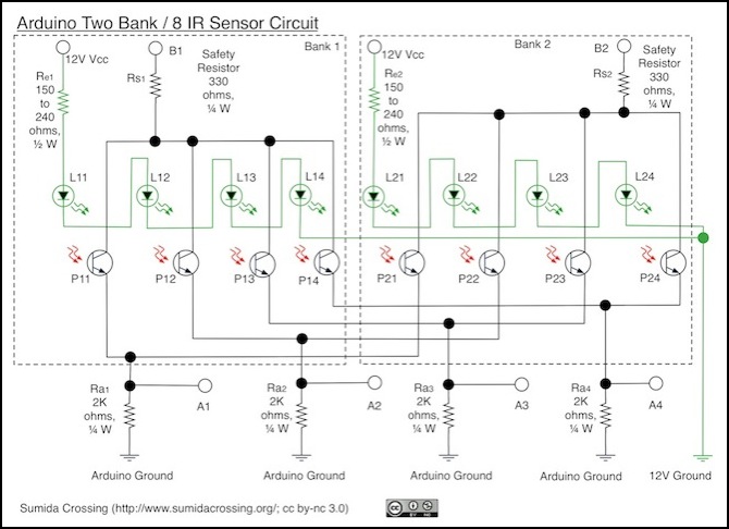
Eight IR sensors (with LEDs) arranged in two banks, using two digital pins and four analog pins
The sensors are placed across two separate “tables” on my layout, with the mid-line station actually at the junction between them, and the two ends on separate tables. This works well, as I can put four sensors on each table and keep a lot of the wiring local to the table. Despite knowing that up-front, I still dithered quite a bit on exactly how to arrange the sensors.
The diagram above shows the currently planned design: eight sensors arranged in two banks. Pins B1 and B2 will be digital, and A1 - A4 will be analog. Each bank of four phototransistors will be connected to a digital pin that provides +5V when high, and each phototransistor to the four analog pins that can be read to determine the voltage passing through the phototransistor.
All four LEDs will be wired in series with one dropping resistor, and connected to a separate 12V power source (probably the layout accessory or lighting bus). These will be always lit (when the layout is powered) and the Arduino doesn’t do anything with them. They’re just a bright (infrared) light shining on the photodetector, which will be blocked by a passing train.
With the LEDs on, each phototransistor will be capable of passing voltage when its digital pin is in the HIGH state, but when the pin is in the LOW state, there won’t be any voltage source for that phototransistor.
I’ve built a four-sensor test breadboard, and have the software to read it working reliably.
I’ve moved the old text on testing the sensors to a more general testing page in the Arduino subsection of the Electricity for Modelers section.
Installation
Each sensor consists of a pair of small blocks that have to be at the height of the train body on opposite sides of the track, making them rather visible. I’m going to disguise these as trackside electrical cabinets, or parts of station platforms, although I don’t think they’ll be completely inconspicuous, but hopefully the moving trams will draw the eye away from them. As I get these built, I’ll update this page with more detail.
