


Easements and Superelevation
This page covers several topics related to track construction that are similar, but not directly related: easement curves, vertical easements, and superelevation. All of these are prototype railroad practices that can be modeled to improve the look of a layout, and the two types of easement have practical application as well.
Easements and superelevation are “technical” topics that often get covered with excruciating complexity. They really aren’t that complex, even in the real world. The math behind the theory can get hairy, but for prototype railroaders this usually was reduced to simple tables anyone who knew basic math could use. And modeling them is much simpler.
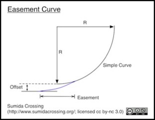
An easement curve, also known as a transition curve, a spiral easement, a spiral or an easement, is a gradual curve starting from infinite radius (straight) where it meets the adjacent straight (aka., “tangent”) track and decreasing in radius until it matches the desired curve radius. This reduces the sideways force (or rate of increase of force over time) applied to a train entering or leaving a curve, which in turn reduces wear on prototype wheels and track and for both prototype and model reduces the potential for derailments. It also keeps the passengers from getting knocked about on every curve.
In practical terms, think of the easement as “spiraling in” from the original straight (tangent) track to meet a simple circular curve. This results in track that becomes tangent (straight) at an offset from where it would have become straight otherwise. Note that where the spiral meets the simple curve is inside the curve, beyond the end (beyond the “point of tangency”). What this means is that if you lay out a simple curve the easement will extend in both directions past the end of that curve, and will extend further out from the radius center than the original curve. Thus eased curves take up space that is both longer and very slightly wider than a simple curve would occupy.
A vertical easement, also known as a grade transition, is similar in that it gradually takes the slope from zero on level ground to match a desired slop on a grade, and that means that it takes a longer linear distance to climb a hill of a given height using a maximum grade.
Finally, superelevation, also called Superelevated track, Canted Track, or Cant Track, is a gradual rise of the outer rail on a curve relative to the inner rail. This doesn’t take any additional space. On a real railroad it’s important for both stability of the train and comfort of passengers. On a model it has no operational effect, but it looks good.
These are all very old railway techniques. Easements were known as early as 1828, although the methods evolved over time and the modern method doesn’t appear to have been known (by railroad engineers) prior to 1880. Superelevation dates from at least the middle 19th century. In modern railroading there are generally limits on speed imposed that depend on the amount of superelevation.
This page collects information on all of these with an emphasis on their use in N-Scale. And while my focus is on Japanese N-Scale at 1:150 scale, the numbers given here are going to be equally applicable to 1:160 scale (or British 1:148 scale, for that matter).
Before I get to the practical modeling aspect, I’ll first provide some background on what the big railroads do, and cover a couple of related topics. Skip down to the Modeling Easement Curves section if you don’t care about any of that.
The Short Form
Some people don’t like to read lots of words, or don’t care about “why”, just “what”, for them I’ll provide the basic answer from the end of this page, streamlined, here. But if you care about “why” or what other options exist, read the rest of the page.
An easement is a section longer than the longest car or locomotive at the end of a curve (each end) that makes the curve longer and wider, “easing” cars into the curve. Easements are important on curves of relatively sharp radius used at higher speeds. They aren’t needed in yards or low-speed station tracks. For N scale, easements aren’t really useful or visually appealing on curves of radius larger than 22” (540 mm) although you can use them if you like.
To lay out an easement, pick a length between 1x and 1.5x the length of your longest car that will still leave 2 or more car lengths of normal curve between the easements at each end of the curve. Draw the full curve at its normal radius. Then pick a point half the length of your chosen easement in from the end and mark it as the starting point for the easement. Pick a second point half the length of the easement down the straight track and mark a point outside it at a distance between 1/4” (6 mm) and 1/2” (12 mm) that looks good (this is the “offset”). Take a flexible metal ruler, lay it on edge parallel to the straight track and through the point you just drew, and bend the other end to meet the curved track at the other point head-on, then trace a line along the edge of the ruler. That’s your easement. Note that this process takes 3 or 4 hands (or some nails to hold the ruler in place). Also it makes curves longer and slightly wider than they’d normally be.
Superelevation is often used on real-world curves, and works well with easements. For N-scale, pick a maximum elevation of 0.040” (1 mm) or a bit less, and cut small shims from standard evergreen plastic strips. Place those under the outside rail (between cork roadbed and the tie) and glue them in place. Do this everywhere on the curve except under the easements. Along the length of the easement, use shims that go from nothing at the straight track to the full height at the end where easement meets curve evenly (so if you use 0.040” on the curve, you’ll have 0.010” a quarter way down the easement, 0.020” at the midpoint, and 0.030” at the 3/4 mark). Put some extra shims in beyond just those three points to avoid having the track sag. That’s all there is to it.
References
For additional information on prototype practice, a 1908 textbook is available online, and covers both superelevation (pg 108) and easements (as an aside on “spirals” in the discussion of curves on page 294). This is probably somewhat dated compared to modern practice. There’s also a 1913 railway textbook on the actual construction methods for surveyors available online (Google Books, select “download as PDF” on the gear-shaped menu icon to get a copy). This explains how the real-world spirals differed from the ideal mathematical ones in the first half of the twentieth century (later practice changed) as well as covering the basic theory and providing tables for railroads to use when constructing them.
For modelers, the NMRA has a lengthy discussion of both superelevation and easements in their D3b series of Data Sheets. These aren’t available to non-members. But the paper copies I have (dated 1999; I haven’t used them in a while) don’t discuss N scale anyway, although the math is there to work it out yourself and there are diagrams that supposedly help select an appropriate superelevation for a given curve, although I’ve never been able to understand them. John Armstrong’s book, Track Planning for Realistic Operation (Kalmbach) also covers this topic, in a more practical manner.
The European Union of Model Railroad and Railroad Friends (MOROP) provides a simpler approach in NEM 113 (PDF). This is covered in more detail below.
If you want a brief overview of real-world practice, there’s a very compact description of the way American railroads surveyed and constructed easements on this website.
If you want to get into the mathematics, what modern railroads use for easements is a common technique, also used by road builders and surveyors, called a spiral curve. There’s a good description here, but you can find lots more information by googling that phrase.
Note: from a surveyor’s perspective, highways use a method called “arc spirals” to construct these curves (if they use them at all, often compound curves are used) while railway surveyors typically use “chord spirals”. This affects what formulas are used to lay out intermediate points along the spiral, but doesn’t change the overall approach. I’m dealing with chord spirals here, but the difference is very small.
Prototype Practice
On real railroads, easements are in use almost anywhere. The sole exception is likely very low-speed trackage in yards or street-running. Similarly superelevation is used anywhere trains round a curve at even moderate speed, and there are often strict limits placed on speed through unelevated curves.
Railroads refer to easements most often simply as “spirals” or “spiral curves”. This is, as noted earlier, a common technique known to anyone surveying a road or railroad. In earlier times there were reference books giving specific easements to be used under various conditions, like the textbook cited above. Today, computers normally do the work.
Mathematically, an ideal easement is an Euler spiral, also known as a “clothoid” or Cornu’s Spiral. This is a curve that has a radius that changes linearly with distance along the curve, minimizing the rate of change of sideways forces on a vehicle proceeding through the curve. These are complex to deal with mathematically. A cubic polynomial can approximate such a curve, and that is what railroads used in earlier times (some may still use them), so the phrase “cubic spiral” is often used. In older texts “cubic parabola” was used to mean the same thing. Modern CAD software used by railway designers uses a true Clothoid Spiral.
Actually, the clothoid isn’t ideal, as it still affects a train entering and leaving the easement due to some complex issues around the way flanged wheels interact with the rail. Curve derailments most commonly occur on easement sections (although without easements, they’d occur where the curve met the straight track, and there would be more of them), so there’s reason to want to improve the design of easements to minimize these effects. Even in the early part of the twentieth century it was recognized that the place where the spiral met straight and curved track had to differ slightly from the ideal to avoid a sudden shock as wheels entered the spiral in either direction. Methods for laying out spirals thus included provisions for dealing with this.
In the last fifty years there has been some research on alternatives, and newer systems may well be in use. Clothoid-based spirals still widely used though, and the alternatives are likely similar enough from a modelers perspective, so I’ll stick with covering them.
Even without the practical necessity of dealing with real wheel and rail geometry, there is no single “right” spiral curve. The shape of the curve is precisely defined by mathematics, but this depends on two basic characteristics: how long it is, and what radius of simple curve it is meeting. The length of the spiral is normally chosen based on the maximum speed to be supported through the curve. Radius also is related to speed, so you could say that the length of the spiral depends on the radius, but in practice there can be a significant amount of variation from one railroad to another.
The reason speed matters is that the spiral creates a different rate-of-change in the sideways acceleration of a train going through the curve depending on the speed of the train. And the purpose of the spiral is to keep that rate within some chosen limit. But the limit has varied between railroads and over time, so the length chosen by one railroad line wouldn’t necessarily match that of a neighboring railroad. And the same railroad today might have a different preference for length than it did a century ago. Even the way the ideal spiral curve is approximated by surveyors laying out track has changed over the years.
History of Spiral Curves
According to The History of the Derivation of the AREMA Spiral, by Halsey G. Brown, P.E., the modern definition using a clothoid curve has been in use in the U.S. since 1947, when the American Railway Engineering and Maintenance-of-Way Association (AREMA) replaced the previously-used “10 Chord Spiral”, which had been in use since 1911. That was a method more suited to design done in the field based on simple distance measurements, and was based on a spiral defined by civil engineering researchers C. L. Crandall and Arthur Newell Talbot, which the latter described in his 1899 book The Railway Transition Spiral. This curve was defined by a cubic polynomial (called a cubic parabola in texts from that time), and a variety of forms of these had been in use by railways. This is sometimes know as the Crandall, Talbot or Holbrook spiral.
He further notes that an earlier author credits Arthur Wellington, a railway and civil engineer, as originally proposing this curve as a transition curve, although there’s no known text or paper of his that does so. Wellington’s long been a hero of mine; I have a copy of his 1899 textbook on railway economics. So to find him in the middle of this history is pretty cool.
Unfortunately, he may not have really been the originator, as Talbot credited the idea to use by engineer Elliot Holbrook on a railroad in 1881, who had also written an article about it in 1880. Unless Wellington had suggested it before then, he wasn’t the originator, Holbrook was.
There were other, non-spiral, transition curves in use prior to 1881. And mathematically the spiral curve goes back to James/Jacob/Jacque Bernoulli, who defined the “elastic curve” some time prior to 1700.
Spirals as an easement are fundamentally defined by the radius of the curve they meet and the length of the easement chosen by the designer. Given those, the shape can be derived. But in the early days, every railroad, and sometimes every surveying engineer, chose the length differently because it depends on how fast the trains are expected to be going, and how much sideways lurching is considered acceptable.
With increasing use of standards created by bodies outside the individual railroads, such as AREMA in the U.S., the preferred lengths of spirals have become more uniform. They still depend on top speed allowed through a curve. And individual railroads may still have different preferences for maximum allowed rate of change in sideways acceleration. But for a given radius and top speed, it’s more likely now that two railroads will use the same length of spiral.
Spiral Curves
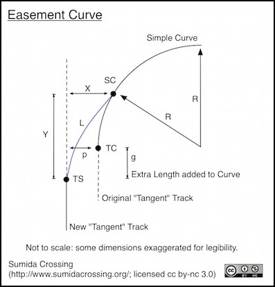
Spiral curves are defined by their length, usually indicated by the letter “L” and by the radius of the simple curve they meet, given as “R”. One important characteristic of these is the additional distance the spiral extends to the side of the route straight track leading to it would otherwise take. In texts this is sometimes called “p” as in the diagram below. But in general offset of a point along the spiral is designated as “X” and the offset at point TC (i.e., “p”) is designated as Xo. Just to confuse things some authors swap, Y, normally the length along the tangent line to a point parallel to the end of the spiral at SC with X (so X means length and Y means offset). In addition “O” is sometimes used in prototype discussions to mean the same thing as “p”.
While the word “offset” usually applies to any offset, modelers often use this word to mean distance “p” and call it “X”. This means that formulas used by modelers often use a different definition of “X” from prototype or abstract mathematical discussions. Neither is wrong, they’ve just chosen different points at which to calculate X. So be careful when reading descriptions that provide “offsets”, as the author may not tell you which kind of offset is meant, and “X” is a significantly larger number than “p”
The length of the easement, designated L, is another problematic dimension. In formal mathematical terms, it’s the length along the curved path of the easement. Most modeling discussions, and some prototype ones, simplify this to a linear dimension, either from TS to SC (i.e., a chord), or from TS along the tangent line to a point parallel with SC (i.e., “Y”). Those are three different meanings for “L”, so again it’s important to know which is meant by an author, and they’re not always clear. It should be noted, however, that in most cases the difference is extremely minor, less than one part in 5000 for a one-degree curve, which is less than a foot of length. For modeling purposes L, Y and the chord length can be considered the same.
The offset (X at any point, including p) of the easement is mathematically derived from the length (see formula for Xc here). Normally length is looked up in a table, while offset is a very simple calculation: Offset at distance Y’ from TS = Y’^3 / 6RL, where L is length to SC, Y’ is length from TS to the point of interest and R is radius. (this formula may be specific to English units; I’m not certain, but it appears to be the formula for a cubic parabola).
The overall length of an easement is primarily dependent on speed, with a lower bound related to the time it takes a train to traverse the spiral (easement) at the maximum allowed speed. This in turn is based on an assumed maximum sideways force allowed. You can calculate length from time and speed if the railroad defines their spirals using time (simply distance = speed / time).
Or you can calculate it from allowed sideways acceleration. The math to approximate this as a cubic spiral is actually fairly simple (I only have one for English measures though): Length (in ft) = 3.15 x V^3 / R x C, where V^3 is the cube of speed in mph, R is the radius in feet and C is the allowed rate of lateral acceleration change in ft/sec^3. For highways, C = 1. The FRA (PDF, pg B-3) sets this to 1.29 for trains (0.04 g/s). So an FRA spiral on a one-degree curve for 100 mph would have a length of 426 feet (130 m).
Note that there’s also a minimum length: an easement needs to ease the car into the curve, so it must be at least as long as the longest car to be handled. One set of U.S. commuter railroad standards I saw set the minimum at 100 feet (30.5 m).
Japanese Ministry of Land, Infrastructure, Transport and Tourism (MLIT) regulations are somewhat simpler (PDF, see pg 18). The length of the easement is derived from the superelevation used, and ends up being around 60m (~200 feet). This seems to be the modern regulation anyway; as noted below the actual math used likely follows one of the spiral formulas, and is simply required to remain within the bounds set by the regulation.
As a general rule the linear length Y is split so that half is between TS and TC and half between TC and SC (i.e., length g above is 1/2 Y). I couldn’t find a mathematical statement of this anywhere, but the numbers always worked out that way and it was mentioned without support in a couple of places.
Prototype Superelevation
There is a fairly simple formula for calculating the needed superelevation for a given speed: E= 0.000685 x S^2) / R, where E is elevation in inches, S is speed in MPH, and R is radius in feet (see below for a different one for metric use). However, in applying it you’ll quickly see that it produces very large numbers for even moderate curves, and there are limits to just how much superelevation can be used for high speed before it becomes impossible to traverse the same curve at low speed. At even moderately fast speeds the problem then becomes that of determining the fastest safe speed for a given radius and superelevation.
On modern prototype railroad track (and this has been true back to at least 1913) the maximum superelevation is limited to about 6 inches (150 mm) due to the need to also support low-speed operation. The risk of derailment increases significantly when the difference between ideal and actual cant exceeds about 1/10th the track gauge, or 144 mm (5.7”) for a train on standard-gauge track. There’s some variation in that: wikipedia reports that some European passenger-only lines use a maximum 180 mm (7”), while South Australian regulations I found via Google limit the maximum to 120 mm (4 3/4”).
I’ve seen conflicting information on this for the U.S. which suggests that the FRA allows up to 8 inches (203 mm) of superelevation on Class 1 & 2 track (low-speed freight only) and 7 inches on other classes (the class of track relates to how carefully it is maintained and to allowed top speed). But for the most part, most sources use 6 inches (150 mm) as the normal maximum outside of high-speed rail applications, except where rules based on track gauge apply.
Note: I’ve read that while the maximum superelevation is normally 1/10 the gauge, high speed rail lines in Europe and Japan use 1/8, which would be 180mm (or 7”), which is in keeping with the number cited by Wikipedia. Note that for a Japanese commuter line of 1,067 mm gauge, this means the maximum cant is 133 mm or 5.25”.
The Japanese regulations (PDF, see pg 15) lay out formulas for calculating cant that are based on the track gauge, train speed, and the height of the center of mass, and notes that the change from uncanted track will be gradual and will occur over the easement curve, the same as U.S. practice. The regulations I found don’t appear to set an explicit maximum, but the formula for center of gravity will tend to keep the maximum to around 150 mm or less (it could be 180 or more with a very low center of gravity, which presumably Shinkansen have). The key formals are Cant (in mm) = G x V^2 / 127 R and Cant = G^2 / 6H, where G is track gauge in mm (1372 or 1435), V is speed in kph, R is curve radius in meters, and H is height above railhead to center of gravity in millimeters.
A given superelevation is only ideal for a single speed. So there’s also a “safety factor” used in calculations, that permits higher and lower typical speeds for trains. In the U.S., this is defined as 3 inches, so with 6-inch superelevation speeds up to those matching a nine-inch superelevation are allowed.
On a modern railroad, the transition from unelevated to fully elevated is quite long. A typical formula (Length in meters = 0.0111 x (cant or cant deficiency in mm) x (max speed in kph), taken from an Australian specification for non-high-speed rail) gives a length of several hundred meters for typical urban-passenger speeds. This is still shorter than the easement, so normally the superelevation will increase along the length of the easement and no additional space beyond either end is required.
Prototype Easements
Putting this all together, the length of the easement is chosen to meet the operating requirements of the railroad, and fundamentally this is based on the speed of a train and the radius of a curve.
Length turns out to have a fairly simple definition in U.S. practice (this is per the 1913 textbook cited above) which is Length (in feet) = (E/2) x (22/15) x V, where E is maximum superelevation in inches and V is maximum speed in miles per hour. An equivalent metric formula is Length (in m) = (E/5.08) x (V/3.6), where E is in centimeters and V is in kilometers per hour. Both of these assume a maximum rise of superelevation of 2 in/sec (5.08 cm/s), but you can obviously use the same formula with any rate of superelevation change.
As an example, let’s assume a typical American freight line with passenger service, and a curve of one degree (radius 5,730 feet or 1728 m) with a top-speed train traveling at 60 mph (95 kph) and a superelevation of 6 inches (15 cm). This yields an easement length of 264 feet (80.5 m). In N-scale, that would be about 1.5 feet or half a meter. That’s quite long, but then that’s for a curve with a radius of 35 feet (11 m). Obviously, as scale curves are smaller so too will their easements be smaller. We’ll cover that below.
The Japanese formula is even simpler: Length (in meters) = 300 E, where is E is cant in meters. There’s a different number for long-wheelbase vehicles (i.e., most commuter/freight lines, which still allow four-axle freight cars) where L = 400 E. However, for high speed use (speeds over 200 kph), the length is increased to L = 450 E. Thus the longest easement on a Shinkansen line would be 81m (266 feet) based on 180 mm of superelevation (E = 0.18), while a commuter line curve with E = 75 mm would have easements of just 30 m (98’). The end result isn’t much different from the American system.
According to a support page for Autodesk CAD software, what Japanese railroads use for an easement isn’t actually a clothoid spiral but a “Sine Half-Wavelength Diminishing Tangent Curve” (and isn’t that a mouthful), the formula for which is quite long. However they’re also known to use a “cubic spiral” that follows the formula x = (y^3 / 6RY), where Y is the tangent distance from TS to a point parallel to SC, as shown in the diagram above. Note that this is measured along the straight line Y, and not along the curved distance L as in the formula for a cubic parabola up above.
In the 1913 textbook, the author simplified things even further by choosing four “standard” lengths of easements: 150’ (45.7 m) for most curves and 300’ (91.4 m) for “high speed” lines (high speed back then was probably around 100 mph or 130 kph). He also added tables for 225’ (68.6 m) and 450’ (137.2 m) to allow designers to be a little more flexible.
Modern practice as defined by AREMA calls for longer easements. In part this probably derives from the higher center of gravity of cars like double-stack containers and multi-level auto-rack flat cars, not to mention two-level commuter passenger trains. And modern easements are designed with CAD software, so approximating them with calculations easily done in the field with paper and pencil are no longer required. For that reason what’s in that 1913 textbook is now obsolete. However, from a modeling perspective the two aren’t different enough to matter.
Modeling-Related Topics
The following sections provide a foundation for the discussion of modeling easements and superelevation.
Sectional Track
There is now sectional track made with superelevated curves, in particular Kato’s line of double-track curves. These come with 22.5-degree curves at each end that provide the superelevation easement, as well as 45-degree curves of superelevated track.
Some modelers using sectional track create easements by mixing different curve radii (e.g., start with a much larger radii, then step down until you reach the desired radius, such as going from straight to one section of 22-inch radius before starting an 18-inch radius curve). This replicates the “compound curve” approach to easements used in the mid-nineteenth century. That’s not a bad approach, although ideally you’d need to use fairly short curves to fit multiple different radii in just over the length of one long car.
I am not aware of any sectional track manufacturer making easement curves or vertical easements. The latter can be approximated with short sections of straight track and careful attention to the curve of the roadbed and subroadbed.
One rule of thumb for sectional track related to easements is: never go directly from a left curve section to a right curve section (or vice versa), but always have a straight section as long as your longest car or locomotive between them. This eliminates S-curves, which can be very bad for reliable train operation, particularly with body-mounted couplers as the sharp angles between them can lead to decoupling or sideways forces that will derail a car. This is essentially the same problem that easements solve for single curves, and when easements are used they naturally provide the protection between two adjacent curves, so you don’t need to add a straight section to break up an S-curve when true easements are used. However, sectional track isn’t a true easement, so use of simple curves with a long straight is going to be preferable to two compound curves without a straight for breaking up a sectional S-curve.
On the whole, it’s difficult to make both easements and superelevated track with rigid lengths of rail provided by sectional track systems. For this, flex track, or even hand-laid track, is needed. The rest of this page will focus on how these should ideally be formed, and to what extent that can be approximated with flex track.
Curves
Before getting into easements and superelevation, it’s worth saying a few general things about curved track. If you don’t get the basics right, optimizations like easements are of little value. This is covered in more detail on the Curves page in this section.
One of the most important aspects of a curve is choosing an appropriate radius. But before even that getting the track level and smoothly curved is vital. The subroadbed (and the roadbed atop it) must be level side-to-side, and if there’s a grade it must be constant except for any vertical easements at beginning and end. And the subroadbed must be supported sufficiently. Even plywood will deform under its own weight over time, and thin plywood or other materials may be more subject to this. Pick a good subroadbed, and follow the guidance in track planning texts or online for properly supporting it.
And while flex track has a tendency to form a smooth curve, don’t count on that for the final alignment. Mark out the curve you want, at the centerline or at one edge, and be sure the track lines up with that before you fix it in place with glue or other methods. Also, if you can, avoid track joiners within curves and particularly at the ends or within easement sections. Link the flex track to straight track well before the curve starts (a car length or more) and put any needed joints in the middle of constant-radius sections (e.g, in the middle of the curve). For short curves, make the whole thing with one piece of flex track, even if that results in some being wasted on the sections of track on either side.
Finally, once installed check that the track is still properly curved and doesn’t have any irregularities or sharp angles before ballasting or doing anything else. It may seem a waste to rip out a section of newly laid track and do it over, but think about how much more painful it will be to rip it out once it’s ballasted and sceniced if you find it causing problems.
Turnouts
If a turnout (track switch) needs to be placed on a curve, it’s not going to be practical to superelevate the curve since the inside and outside rails meet at the frog.
Turnouts also have a fixed radius of curvature (or a sharp curve and a straight, which is worse), so they can’t be placed within the easement portion of the curve even if superelevation weren’t used. Unless, that is, you are using the compound-curve approach to easements described in the sectional track section above.
Turnouts on curves are thus something to avoid, and if you have to use them for space reasons, then you need to give up on superelevation for that curve, and possibly also on an easement if the switch is near an end of the curve.
Modeling Easement Curves
As mentioned above, an easement is desired at the start and end of a curve, to avoid abrupt increases in sideways force that could derail a car. The purpose of an easement curve is to “ease” the train into the curve gradually, minimizing the change of angle at couplers between cars, and the resulting forces on the wheel sets nearest those couplers.
Do you need easements? No, particularly if you use large-radius curves or operate at lower speeds (e.g., a logging railroad isn’t likely to need any easements). But if you run long cars into tight-radius curves, an easement can make the difference between rounding the curve and derailing. Easements also have a visual aspect. A sharp transition from straight track to curved track can look more toylike and just plain wrong and a long car running into such a curve will tend to lurch abruptly sideways, which is not at all realistic. Note, however, that low-speed street trackage and yard tracks aren’t as likely to have easements on the prototype (they can though), and the extra space required makes adding them on a model railroad problematic in these situations.
The basic idea of an easement is that it has a rate of change of curvature that relates to its length and the speed of trains using it. If trains are moving at higher speeds, or the curve is sharp, you want a more gradual change (i.e., a longer easement) than if trains are slow or curves are broad. Thus the amount of easement in a freight yard curve is going to differ from that of a light-rail line (similar speeds, different curves), and both will differ from a mainline curve optimized for moderate speed freights, which in turn differs from a similar curve intended for high-speed passenger trains.
Since the purpose is to ease a car into the curve, the overall length of the easement needs to be longer than the longest car or locomotive using the track, and a good rule of thumb is to make it about 1.5 times that length, but we’ll cover length more below.
A model easement doesn’t need to be as big as a prototype one, because the forces involved are different, and there aren’t any people on the train to be thrown sideways. There are a couple of methods for deriving model easements.
As mentioned earlier, a typical prototype easement from the early part of the twentieth century was 150’ (45.7 m) for most curves and 300’ (91.4 m) for higher-than-typical speeds. These equate in N-scale to 11.25” (286 mm) and 22.5” (572 mm), or about twice the lengths typically used by modelers. This could simply be that most modelers are modeling relatively low-speed trains, but this doesn’t quite make sense, as the shorter (11.25”) one was already for low-speed freight lines. Rather it’s likely that trying to match prototype easement length on a curve that’s much sharper, and thus shorter, than a prototype curve, would simply end up having the entire curve be easement, or at least more of it than looks good. So we need shorter easements, but how much shorter?
Simple Scaling
One idea is that an easement takes up a certain arc of a curve. For our earlier example of a one-degree curve with an easement of 264 feet, consider that a circle of that radius has a circumference of about 36,000 feet (100 feet per degree), so the easement is 2.64 degrees. If we take that and use it with a broad N-scale curve of 18” radius (457 mm) it equates to an easement of length 10.5 mm (about a half-inch). That’s much, much shorter than a single car. So it won’t provide any benefit operationally. Nor is it likely to have any visual appeal.
What this means is the for modeling purposes, the minimum easement length, which is the length of one car, is also a reasonable maximum length. However, as we’ll see below, most authors have chosen to use longer easements on model railroads, likely for visual appeal.
The John Armstrong Method
If you don’t already have a copy of John Armstrong’s Track Planning for Realistic Operation (3rd edition, Kalmbach, 1998), and you’re serious enough about model railroad design to care about things like easements, go buy one. Don’t worry, I’ll wait. Actually all he says about it is contained in one sidebar on page 116, but it’s a fairly dense sidebar, and it’s worth having the book for other things as well.
Armstrong lays out an approach that defines three easement curves: Sharp, Conventional, and Broad. In N-scale these correspond to track radii of 9 3/4” (248 mm), 13” (330 mm) and 16” (406 mm). These have linear lengths between TS and SC in the diagram above of 6” (152 mm), 8” (203 mm) and 10” (254 mm), and offsets (p) of 3/16” (4.8 mm), 1/4” (6.4 mm) and 1/4” (6.4 mm). And that’s not a typo, “p” is the same for conventional and broad curves.
In a sense, what Armstrong is doing is following the early twentieth century prototype practice of using standard lengths of easement curves rather than building each to fit the specific curve. Modelers of low-speed freight lines will tend to use sharper curves, and thus choose his Sharp (or perhaps Conventional) curves, while modelers with passenger service will want broader curves to accommodate long cars, and thus choose his Broad easement size.
The XTrkCad Method
The XTrkCad program uses a similar method to John Armstrong, although not exactly the same dimensions (I doubt this is a coincidence given how influential Armstrong was and is). They define Sharp, Normal, and Broad easements (in file xtrkcad.xtq, see the wiki for a definition) using the same three values (R, X, and L) given in prototype inches. I presume these get mapped to actual curves by dividing by the scale and then scaling proportionally to the actual radius. Under that assumption, these appear defined to best fit 9.75” (248mm), 13.75” (350 mm) and 16.5” (420 mm) curves in N-scale, and for those yield easement lengths of 7” (178 mm), 9.375” (238 mm) and 11.75” (299 mm). Also, their “f” can be up to 0.375” (9.5 mm) for the largest radius noted.
The MOROP Method
The European Union of Model Railroad and Railroad Friends (MOROP) provides a simpler approach in NEM 113 (PDF). This has a fixed offset of 4mm for N scale, and a length calculated from the radius of the curve: Length (mm) = SQRT( Offset x 24 x Radius), with all dimensions in mm. This is somewhat simplified (for example, they treat L as a linear distance along the path of the tangent track rather than a curved distance along the easement curve), but is close enough for modeling purposes. They note that easements really aren’t necessary for curves of radius 60x the gauge or more (540 mm in N, or 21.25”).
For Armstrong’s curve radii, the MOROP method calculates lengths of 156 mm, 178 mm and 197 mm. For the three XTrkCad radii it calculates lengths of 154 mm, 183 mm, and 201 mm. So it is clearly producing a sharper and less space-intensive set of easement curves than the Armstrong method. This makes sense as European layouts tend to be smaller and more space-constrained than North American ones.
Choosing an Easement
For higher speeds, easements will tend to be longer, so none of these approaches is really perfect. But there are limits to this: if a curve ends up being mostly easement, it can look subtly wrong. An easement that’s too short, on the other hand, is also going to both look wrong and not provide the full benefit. The easement needs to be at least as long as the longest car, and a good rule of thumb is 1.5 times the longest car, but there needs to be a generous portion of curve between the easements at each end, typically several car lengths.
Within those bounds, choosing a specific easement offset and length is essentially a matter of taste. You can use the Armstrong, XTrkCad or MOROP methods, or just do it by eye. The shape of the easement within those bounds is governed by precise mathematics, but fortunately for those of us bad at math, it happens to roughly match the shape of a bent wooden stick or flexible metal ruler, so once you pick a length and offset, and mark points for them equidistant along the line of tangency from point TC, it’s easy to draw the path the track must follow by tracing along a suitable object curved between those points and lining up with the track at both ends.
Model Railroad easements, despite all the words I’ve used here and all the math people normally throw around, are remarkably simple when you get right down to it.
Modeling Superelevation
The purpose of superelevation is to reduce the sideways force of wheels against the outer rail, converting part of it to a downward force due to the angle of the trail caused by raising one side. This affects both the stability of the train at speed, and the wear on the track and wheels from friction due to sideways force. It also has an effect on passenger comfort. At even mild speeds the sideways force around a curve can be disconcerting, or even unpleasant. Superelevation alone won’t solve this problem at higher speeds, which is why tilting trains are sometimes used on very curvy track.
Note: Kato’s banked track has a superelevation of about 0.035”, which equates to about 140 mm or 5.6 inches in 1:160 scale.
On a model, superelevation serves no functional purpose: the weights and forces just don’t work the same way as on the prototype. It’s purely there for visual appeal. Comments I’ve seen online suggest that it is visually appealing and generally does not pose a problem for operation, although with very tight curves and heavy cars, there could be some risk of toppling inwards (“stringlining”). However opinions on that vary. Some also feel that many modelers over do it, with six-inch superelevation on track that doesn’t really warrant it.
Not all track is necessarily fully superelevated, particularly if it serves a moderate-speed freight function. And even on an N-scale model, 6” (150 mm) of superelevation is very visible in its effect, particularly with tall smooth-sided cars (e.g., double-height passenger cars, double-stack containers, etc). So it may be a good idea to differentiate lesser lines by using about a 3” superelevation (i.e., making shims about half the size noted below for 6-inch).
As a reasonable approximation, a typical superelevation of six inches (150 mm) equates to about 1 mm or 0.04 inches in N scale. For high speed rail, 0.045” (1.14 mm) could be used. This is actually very convenient, as narrow strips of plastic are available in a variety of thicknesses up to 0.040”, and these can be used to make shims under the outer rail of flex track to transition from the level up to the desired elevation. Keep in mind that this is difference between inner and outer rail, and placing the shim under the ties causes both rails to lift; the difference in rise between them depends on the length of the tie and the placement of the shim. As long as ties are the same length, it’s only important to be consistent in where the inside edge of the shim falls relative to the rail. But if you change the tie length in the middle of a curve, you’ll need to be more careful.
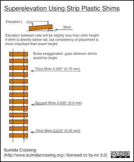
Some measurements of typical ties suggest that if the inside edge of the shim is directly under the rail, the shim needs to be about 0.055” to produce just under 0.040” of effective superelevation or roughly 6” (150 mm) of 1:160 scale superelevation, and that 0.060” is slightly less than 0.045” of effective superelevation, or roughly around 7” (180 mm) in 1:160 scale.
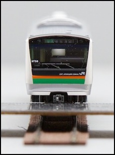
Track with no shim, with 0.025” shim, and with 0.055” shim
In the prototype, superelevation begins well before the curve does, so that the change of level is gradual, but on entering the curve the train will immediately benefit from the effect. Exactly how this is done can vary. The 1908 textbook referenced above notes (pg 110) that it’s typical to begin 25 to 50 feet before the curve for each inch of rise needed within the curve. This is qualified to note that this is without taking into account spiral easements, and it likely also makes some assumptions regarding both speed and train height and weight as the numbers are smaller than those used in modern railroading. The textbook notes that with an easement curve, the superelevation begins with the easement, rising to full height where the easement ends.
On a model railroad the transition from no elevation to the maximum may need to begin prior to entering the easement curve. The NMRA (in their data sheet) recommends distances of 100 - 200 scale feet before the start of the easement, equating to 7.5” to 15” (190 to 280 mm) in N scale, assuming I’m reading them correctly. They may just be saying that’s the minimum length of the superelevation transition.
Modeling Vertical Easements
When model railroad track changes from horizontal to a grade (up or down), this needs to be gradual in order to avoid cars uncoupling. And with steep grades, locomotives with snowplows or “cow catchers” on the front hitting the track with them is also possible on sharp transitions. I once built a 5% grade only to later discover that one of my models with a front mounted snowplow would short the rails every time it tried to climb the grade.
The normally modeling solution to this problem is very simple: use plywood subroadbed, and ensure it has no joint near the change from level to grade. When one end is raised, and the other held level, the plywood will naturally curve gently to meet the grade, forming an easement. This may not be as smooth as is needed, but you can vary the sharpness by adding risers along the curve to fix it in a given shape if needed. Build it, then test with appropriate trains before adding scenery.
If you are working with something more rigid, such as Woodland Scenics foam risers and inclines, then what you need to do is have an initial section at least one car long at a lesser grade. E.g., if you have a 2% grade, use 1% for the first car-length, or use 0.5% for one car length, 1% for a second and 1.5% for a third. Again, you’ll need to do some testing, but here you might have to rip out some of the track and incline and re-lay it.
