


TestTrack
Test Track Construction I - Plan to Roadbed
After entirely too long dithering about, it’s time to actually lay some track. Or at least, begin the process.
As I mentioned in my earlier post on Planning a Test Track, this is going to replicate the crossovers west of Ochanomizu Station, which will allow me to test prototypical signaling, as well as operation of trans through some complex crossovers on my planned code 55 rail. If I’m going to have problems with that, this is where I want to discover it.
First, I made some basic tests, running cars by hand on Micro Engineering Code 55 flex track, both with wood and concrete ties. This was just to determine if typical wheels would have problems with the low profile (e.g., bumping into moulded-on spikes, etc). I tested with Kato, Tomix and Micro Ace models, both passenger and freight, and all worked flawlessly. These were all of relatively recent manufacture, but it suggests that I’ll be able to use code 55 rail without problems.
My fallback plan was to switch to code 70 track if this didn’t work, and that still might happen if problems turn up on the test track. But I’d really prefer to have the lower-profile rail if possible.
Designing the Track Plan
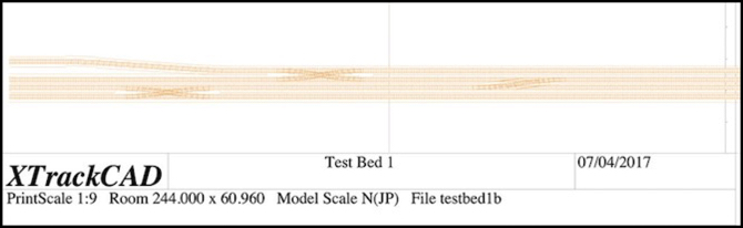
I laid out a track plan eight feet (244 cm) in length, to fit my pair of four-foot long boards. A print of this is shown at the top of the post. For this I just included two #8 double crossovers and a single crossover, the latter made from facing #8 switches. I also tried my hand at widening the inter-track spacing of one line, mostly to see how well i could do this in XTrackCAD (see my XTrackCAD page for details), but it would also provide a test of car behavior on an S-curve (I put a 20 cm straight section between the two curves).
This is slightly compressed from the prototype. The actual distance from the bridge at the end of Ochanomizu station where the half-crossover is located to the second double crossover is about 550 meters, or nearly long enough for three ten-car trains (each of which are about 200 m in length). The total distance on my test board is eight feet, which in 1:150 (Japanese N Scale) equates to about 366 scale meters, slightly shorter than two “200 m” model trains (which are about 4’ 5” each), and the crossings are even closer to each other.
One goal of my modeling is to make the space between stations large enough that a train seems to spend time traveling from one to another. On the original Sumida Crossing my two stations were about 2.5 m (7.5 feet) apart, but that was with a curve, which made the space look even longer. So another purpose of this track is to let me see how models will look on such a replica of prototype track if I do a “scene” of the interlocking between the two stations as a mostly-straight track.
I left a roughly 6” (150 mm) margin on the “front” of the board, and most of the back half is empty. This will provide mounting space for electronics and circuit prototyping boards (where I’ll put LEDs and resistors to fill in for signals). I was also careful not to place any of the switches near the edge of one of the physical boards, so that I could have removable track across the gap of sufficient length to adjust for any minor alignment problems.
Most of the track plan creation followed the same basic process I described in my Learning XTrackCAD post last year, but the S-curve was new. As described on my XTrackCAD page I created this using two eased curves over a total length of about 50 cm, creating a smoothly flowing widening of the inter-track spacing. This looks good, and the numbers seem to be right, but I’m going to have to build it and run some trains through it to be sure it works as well as I expect it to.
One potential construction problem I have is that the 28 mm center-to-center track spacing I’m using is less than the 31 mm width of the base of the Woodland Scenics foam roadbed I plan to use, which will mean I need to trim each piece when creating paired tracks, which will be most of my track. The result is likely to be less than perfect, but I should be able to hide that under ballast, and the outer edges can remain untrimmed.
As I’ve mentioned before, the 28 mm spacing is enforced by the double-crossover jig I’m using (hand-laid tracks, #8 double-crossover). This differs slightly from the 26 mm spacing I’d originally planned to use (NMRA standard straight-track spacing equates to 26.2 mm). For prototype Japanese commuter lines, the minimum legal spacing equates to just over 24 mm (see my Track Standards for Straight Track page for much more detail) and I found spacings much wider than 26 mm looked “unrealistic” to my eye. So 28 mm is not ideal, and I may use closer spacing on the final layout, away from crossovers, which aren’t all that common on most lines.
Transferring the Plan
Having drawn the plan, I then printed it out in 1:1 scale. Doing this was yet another learning experience (the online instructions skip over some of the important details). First, I used page setup in XTrackCAD to select landscape mode, since my layout was long and narrow. I also selected “any printer” and “US Letter” paper, since that’s what I’m using.
Then in the XTrackCAD print dialog, I selected a “Print Scale” of 1, meaning full-size, and set the width of the roadbed outline to 3.100 (it is in cm, as are nearly all metric measurements in XTC). In addition to checking “Print Roadbed” and leaving “Print Rulers” checked (it was on by default), I also checked “Ignore Page Margins”, “Print Registration Marks”, and unchecked “Engineering Data” (which meant I didn’t get page numbers, but I’m aligning these based on the rulers).
The registration marks are important, as you can measure spacing between them and check alignment over longer distances using a yardstick or long board, to make sure minor errors don’t slip in when you place the paper on the layout.
The thing it took me some time to figure out is that you have to “select” areas to be printed by clicking on the main XTrackCAD window after you have the print dialog open. This is useful since you don’t have to print everything, but it is very badly documented and without doing it the “Print” button is grayed out and won’t work.
I then clicked “Print”, which brought up a second window where I could select the printer. Here I selected “Print to File” and PDF format, and “all pages”, which gave me a PDF with all of the layout I’d selected.
Now at this point, things will vary by operating system. I’m on a Mac, so I used Preview to open the PDF and clicked Print, which gives me my Operating System’s print dialog. Here I changed from “Scale to Fit” (the default) to “Scale” and “100%” (the default for the printer I was using was 97%, which would have distorted the measurements). Here you can choose to print subsets of the pages, in case you have a problem and need to reprint one, or are only working on part of the construction at a time.
I did find that some of the track near the edge of the paper didn’t print in this mode. The benefit is that “Ignore Page Margins” means that you can line up the paper edge to edge and the registration marks will be the correct distance apart, which simplifies laying the paper out on the baseboard.
I then trimmed the printed paper so that only the track outline plus some extra bits for the registration marks every 10 cm remained. Holes were punched along the centerline, and then the paper was laid on the boards. Once I was sure it was all correct, a Sharpie was used to trace the edges of the roadbed and the track centers.
Next up: I need to start laying track.
Planning a Test Track
I’ve been thinking about this for about two years now, but it’s finally made it to the head of my “things to do” list: I want to build a short test track using the techniques I plan to use for the new layout: code 55 flex track and turnouts made using the Fast Tracks soldering jigs.
There are several reasons for this: first, I want to refresh my flex-track skills. Second, I want to learn how to use the jigs to make turnouts. Third, I want a fairly complex interlocking where I can try out electronics for detecting trains and controlling signals and interlocking those with turnouts, as well as interfacing all of that to DCC and JMRI running on a computer. And finally, I need to test some trains and see if they have any issues with this type of track.
So the first order of business was to figure out what I want the interlocking to look like. I started by sketching out an interlocking with a couple of tracks and some sidings, which was a nice, generic, interlocking, but not really representative of what I want to model. I’m modeling high-density urban commuter passenger lines in Tōkyō, and those are double-track with few sidings.
So that turned my thoughts to the junction between the Chūō Line and Sōbu Line at Ochanomizu Station, and the set of interlockings just to the west of there, between Ochanomizu and Suidōbashi stations. I’ve done a lot of research on that area, and know the layout of the track and associated signals fairly well. It has a mix of 3, 4 and 5-lamp signal heads, so I can test most and maybe all of the signal types I’d use. Plus it’s a very complex environment, which makes for a good test.
Read More...
