


Kato EMU Disassembly
Kato’s current EMU models fall into two broad categories: those designated “DCC Friendly”, and the prior generation that lacked provision for Kato’s DCC decoders. Both kinds consist of an upper body that fits onto the chassis assembly by friction, and a chassis that consists of the frame, undercarriage, and any interior molding.
All of Kato’s Japanese-outline EMUs (and possibly their DMUs, but I don’t own any to know) follow basically the same design. I’ve used these techniques on E231, E233, and Series 205 commuter EMUs, and both Series 500 and E3 Shinkansen models built between 2003 and 2010.
Caution: Taking one of these apart isn’t really hard, but it does require a delicate touch, and it isn’t a task for the faint of heart, as it’s not too hard to break something, and replacement parts are very difficult to get as nobody outside Japan carries them, and few Japanese sites do. You can try sending Hobby Search an email and asking if they can order them for you if necessary, but I’m not sure if they still do that (I’ve never done it). Work slowly and carefully, particularly if you haven’t done several of these, and watch out for easily broken or lost detail parts. And, as always, your results are your own responsibility. Don’t complain to me if you break a $300 model. You’ve been warned that’s a possibility.
Separating the Upper and Lower Body
The upper body is mostly a shell with plastic inserts for the windows. When installing lighting, a diffuser is clipped to the underside of the roof. To separate the body from the undercarriage turn the car upside down, then gently spread the sides of the upper part near one end using fingernails. If this is a problem, a small piece of index card or similar can be inserted between the body and frame to keep them apart. This requires both hands and several fingers and thumbs, but once you’ve done it a couple of times, it becomes quite easy to do again. When the body separates, pulling gently on the truck and upper body will free one side. Repeat for the other side, then do the same for the other end of the car.
The cab cars are more troublesome, as the end away from the cab must be separated first, then the body pushed gently lengthwise just a millimeter or two to separate the front end (cab) from the plastic light-pipe (yellow plastic on left in photo below) that fits into a slot in it, before the body can be lifted away from the undercarriage. This should not require a lot of force, but the light pipe often sticks, and requires a bit of gentle flexing to free it.
When reassembling a car, the most common problem is the window fixtures getting out of position and preventing the body from going together. This is particularly true on the cab car. Careful use of a small jeweler’s screwdriver or strips of index card may be needed to press the window into position from the inside while sliding the body and chassis back together, although usually this isn’t necessary.
Note: Some models, the Series 500 Shinkansen for example, have a lower body that wraps the undercarriage. This may need to be separated from the upper body (and with the 500, the couplers will typically fall out when that’s done, so pay attention to detail parts like that so you’ll know where to put them back).
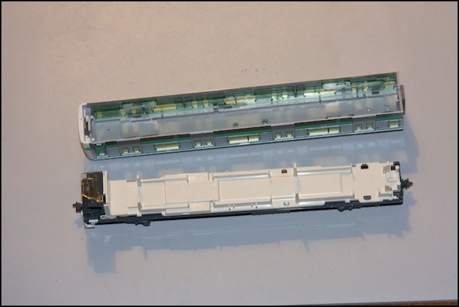
E231 Cab Car with upper body removed
Undercarriage Design
The lower body consists of the floor molding and an undercarriage molding. On the motor car, there is a metal frame in place of the undercarriage molding. On every car, two brass strips run lengthwise, one on each side. These make contact with pins on the two trucks, so they serve as power rails for the lighting, motor, and DCC modules. You normally don’t see these, and you don’t need to take the interior and undercarriage apart to install DCC decoders on “DCC Friendly” cars. But if you are doing a “wire in” decoder install, you may need to take them apart to access the power rails and the lighting contacts.
Note: Kato’s DCC modules fit into spaces on the undercarriage molding, essentially placing them either under it (for the motor) or between it and the interior molding (for the cab decoders). In both cases these are positioned to contact the two lengthwise brass strips.
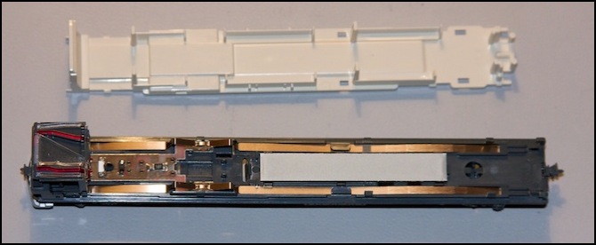
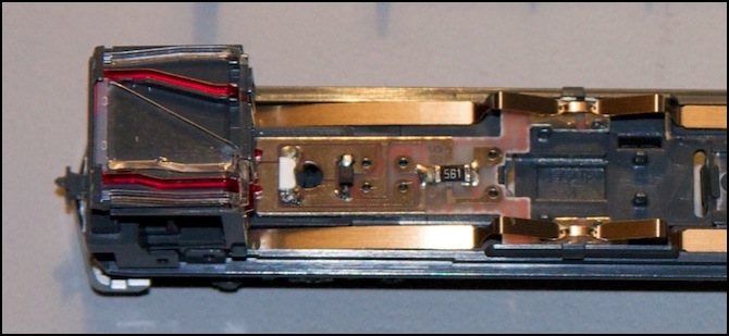
Here is an enlargement showing the top of the cab (left) with the light-pipes to the destination signs, the LED and associated electronics for that (center) and the socket where the cab DCC decoder goes (right). Note how the two through-rails touch the four pads (two on each side) in the socket without a decoder. When the decoder is inserted, it fits between the pads and rails.
“DCC Friendly” E231 Cab Car with floor molding removed, DCC decoder socket is just left of center.
Older Motor Car Take Apart
Kato has two very different designs for the motor cars in pre-DCC and “DCC Friendly” trains. Although the “Pre-DCC” design is for cars designed prior to the introduction of DCC by Kato (c. 2007), many of these designs remain in use, and are even re-used for new designs. A newer set number (e.g., 10-524) is no guarantee you aren’t getting an older design.
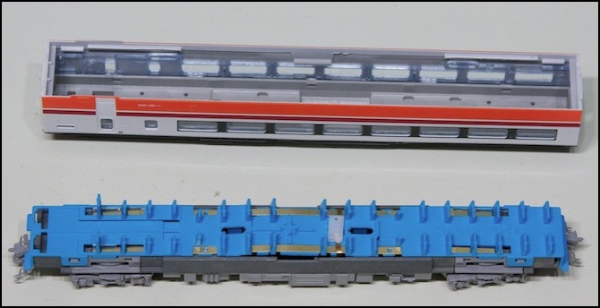
Older Style Motor Car (Nikko/Kinugawa 485 set 10-918) with top removed
The older design can be easily recognized by the white clip (center above) used to hold the two motor contact strips against the side power rails (which in this design run above the floor molding in some places). You wouldn’t normally need to take this apart, but it’s not too hard to do if you must. For a DCC conversion, you just need to remove the white clip, and separate the vertical motor tabs from the power rails (a bit of Kapton tape comes in useful for that).
If you do need to take it apart for some reason, these are the steps:
1) Remove the white plastic clip (don’t lose it!) and bend the motor strips into an upright position.
2) Remove any body-mounted couplers (clipped to the frame if they exist). Most models don’t have these.
3) Unclip the ends of the interior moulding (blue above) from the tabs on the frame or truck inserts (there are four of these, one near each corner). The brass strips will make the ends pop up slightly, which is good.
4) Remove the underside plastic molding in the center (light gray plastic in center below). To do this, squeeze rather firmly at one end until the clips disengage from the metal frame. One end will be easier to do than the other, so if you have problems, swap ends. Once one end comes off, the other will be easier. Note that this version does not slide lengthwise (the “DCC friendly” ones that do don’t have the exposed metal part in the center, and are marked with an arrow). It just lifts off once the clips disengage.
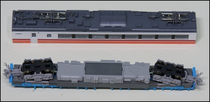
Motor Car upper section and undercarriage
5) With the underside removed, you can see where the interior molding has four clips holding it to the frame. There are two on either end of the motor, flanking the drive shafts (you don’t need to remove the trucks or drive shafts).
6) Very carefully, one at a time, use a tool such as a small flat screwdriver (or one prong of a pair of heavy tweezers, or a plastic “spudger” used with electronics) to push one of the four clips (shown on blue part below) away from the frame towards the drive shaft. When both on one side of the motor have separated from the frame (and it’s hard to tell when that happens sometimes), you can push on one of them to lift that side of the interior molding slightly away from the frame (make sure the end clips were unhooked as in #3 above). Until you release both sets, the interior molding won’t move much (and sometimes you remove one, and the other clips itself back in; patience is required). Be careful, as it’s reportedly easy to break these, although I’ve taken several cars apart without any problems.
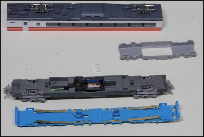
Interior molding (blue) separated from frame (dark gray) and other parts
7) The motor is now held in place only by the two drive shafts. The trucks can be removed by twisting and lifting them gently (they’re only held in place by tabs that rest loosely in the slots on each side, faintly visible in the photo above. Then the drive shafts can be slid out to separate the trucks.
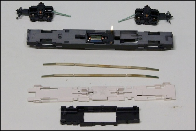
Fully disassembled “Pre-DCC” motor car (not quite identical to the one in the preceding photos)
New Motor Car Take Apart
When Kato introduced their DCC decoders, they redesigned the motor car, making it much easier to work on.
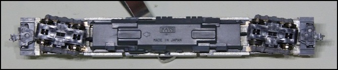
“DCC Friendly” motor car
1) Essentially, all you need to do is remove the plastic housing under the frame. This unclips by sliding it about 2mm in the direction shown by the arrow molded into it (see above), then lifting it away from the frame.
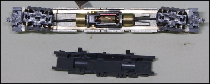
“DCC Friendly” motor car with housing removed
Note: in the photo above, the DCC decoder goes to the left of the motor, and that truck needs to be removed to install it. The other truck can be left in place. For more about that, see my DCC Ready EMU page.
2) The trucks can be unclipped by holding one in one hand, and the frame in the other, turning the truck to one side as far as it will easily go, and then applying a gentle upward twist to pull one side away from the frame. This will pop the clip on the side of the truck out of the slot on the side of the frame, at which point is comes away (and the drive shaft will unplug from the socket in the flywheel). Note that some trucks now have tabs on the bearing point where the truck touches the frame above it (see right truck below), and this makes it harder to unsnap these; turning them all the way to one side is probably less helpful there, although they still have the side tabs that need to disengage. I use essentially the same technique for both kinds.
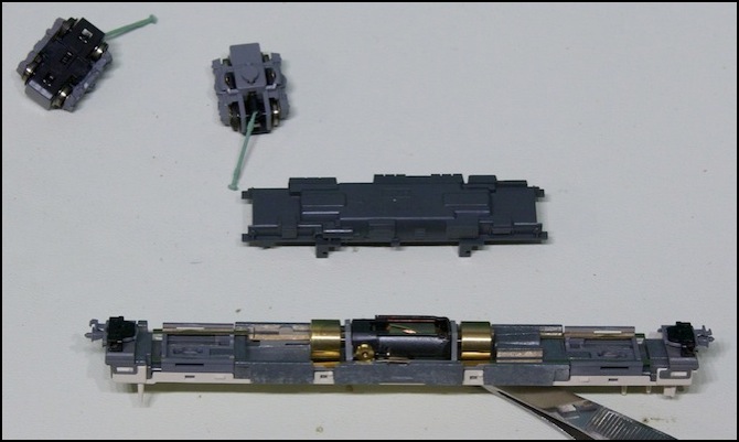
Motor Car with trucks removed (you only need to remove one when installing a DCC decoder)
Because the motor and DCC decoder slot are all on the underside, you don’t need to separate the interior molding from the top of the frame. If you were doing that (e.g., to install a wire-in decoder), you’d need to follow a similar procedure to that used with the older cars to release the clips and tabs holding the two together.
