


Layout Wiring Overview
This page discusses the layout wiring. The actual power supplies are discussed in more detail on the DC Power Supplies and DCC Power Supply pages. See also the Electricity for Modelers top-level section. More detail about the layout track power wiring design is available on the Power Wiring Design page.
Power Supplies
For my railroad, the basic requirements for power supplies are:
- 120V AC power (wall current) to the computer and various power supplies.
- 12V DC for DCC power supply systems (5 Amps per DCC power supply)
- 15V DC for BDL168 and SE8C (dedicated system) (DC bus #1, Signaling & Occupancy Power Bus)
- 12V DC for DS64, PM42 and other DCC accessories (DC bus #2, DCC Accessory Power Bus) *
- 12V DC for LED lighting (possibly per table or other arrangement)
* The PM42 poses a problem, although the manual says it can run on 12-18 VDC, Digitrax’s web site says that it requires 13-15 VDC. Additionally, it can’t share a power source with the power it’s switching, as there will be a momentary outage of the latter in a short. Thus, these cannot be powered from the PS2012 I was going to use for the Accessory Bus.
Now there are a number of ways I could simplify this. I could use separate PS14 power supply transformers for each DCC accessory (up to three devices per PS14 in some cases). In some cases accessories could draw power from the track (or the DCC bus).
I’m a firm believer in keeping things modular to make diagnosing problems simpler. So using track power to supply accessory systems just feels wrong to me. At the same time, I’d rather not have PS14 “wall wart” transformers and wiring all over the place, so a larger combined supply and a “power bus” along the underside of the tables that devices can be connected to is a design that appeals to me. Yes, I’m aware of the inconsistency here. Modularity has limits.
I’d originally planned to have one “DC power bus” to use for all accessories. But Digitrax recommends keeping the SE8C (signaling controller) and BDL168 (occupancy detectors) on a separate power supply from all other systems. They also recommend that the PM42 not share the power supply used for the track. And it makes sense to keep things that may be sensitive separate from a power supply that may have strong transients, such as the one used to throw switches. So I’m going to have a dedicated “Signaling Power Bus” for the BDL168s and the SE8C. The DC64 switch controllers, the UR92 and any powered UP5 panels, and anything else will use a “ DCC Accessory Power Bus” driven by a separate supply. I may also use this to power the Tortoise machines that drive my grade crossing gates.
Beyond this, I’m going to have lit buildings, station platforms, streetlights and other things that need LEDs. A LED can run on any voltage above 2-3 V DC (you just need the right resistor), but to simplify and keep from confusing myself, I’m going to use 12V DC for this. This will allow strings of 3-5 LEDs off one power connection (with one resistor), depending on the type of LED. I found some nice “wall wart” power supplies at a local electronics store, similar to the PS14 but with five times the power (1.5A). These should power a substantial number of LEDs each. I’m going to start with two of them, one for each of the major “scene” tables, but will likely add more later.
Bus Wiring
All of this results in a lot of wiring under the tables to supply the various systems with their appropriate electrical source. In addition to the supply and accessory bus wiring, there’s a DCC power bus to feed power to the rails. But I’m going to complicate that too: because there are three double-track loops on each table, I could potentially have six or more trains running, and they could all be on one table at a time. While that will fit within the output of one DCC supply, I’m planning to provide for later addition of a booster just in case. And that means I need to feed some tracks off one DCC bus, and others off a second.
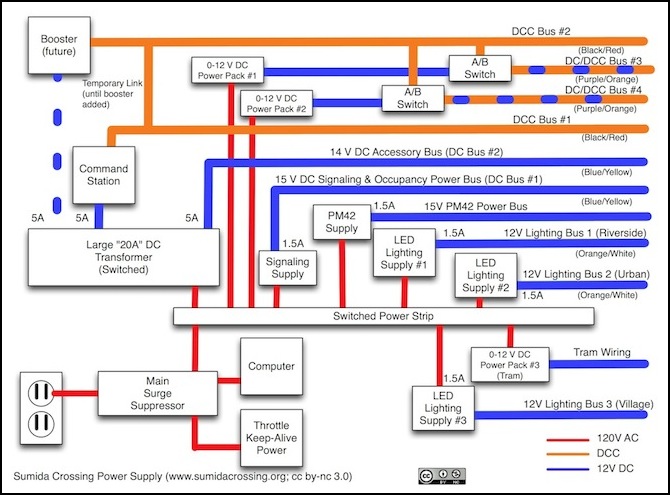
So I end up with two DCC buses and two switchable DC/DCC busses. Plus the two 12V power busses (Signaling and Accessory) and a lighting bus. That’s seven pairs of wires (plus a ground wire shared by all DCC systems). The diagram below shows how these all connect to each other and to their power sources (connections to on-table electronics and feeders are now shown here), and the following sections go into more detail about each of these subsystems.
Initially, the two DCC buses draw from the same 5 Amp, 12 V DCC Command Station, but one can be separated for addition of a booster if desired (this is looking very unlikely at this point).
Layout Power Busses
DC and DC/DCC Track Power Bus(es)
I end up with several parallel sets of “track power” bus wires. These are heavy-gauge, high-amperage connections from the power supply (DCC Command Station or similar) to sections of the layout. Track isn’t fed directly by feeders connected to the bus wires, as I have intermediate electronics (circuit breakers, occupancy detectors, transponding sensors) that need to go in the middle. One ground wire is shared in common by all of these.
To complicate things yet further, I wanted to wire up the two tracks of the Rapid/Shinkansen loop to allow operation with either DC or DCC. An A/B switch will let me switch between a DC power pack and one of the DCC supplies (Command Station or Booster), but that means the output of the A/B switch needs a bus dedicated to one track. Two tracks (for two power packs), means two switchable buses. This is not without issues (see the discussion in the Track Bus section of the Power Wiring Design page), and I might re-think this later, but for now that’s the plan.
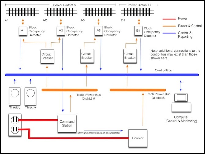
Reliable train operation depends on a consistent supply of electricity to the train. Both long runs of rail and thin wires cause voltage drops due to resistance, which can cause a train to run badly, or not at all. Wiring of any complexity is also prone to failures, and there is little about model railroading less fun than trying to track down the cause of an electrical fault when you want to be running trains. For these reasons, the wiring that supplies electricity to the track is very important to the enjoyment of the model railroad. The Wiring for DCC website provides a lot of useful information about what matters, and how to approach the task of wiring a model railroad (and much of it is applicable to DC operation also). I have my own opinions, so the final system differs in some particulars from what is outlined there, but in general it’s a very good source of real-world information.
Below is a diagram for reference. For power wiring, I’ll be discussing the orange sections alone.
My track voltage has a nominal value of 12.0 Volts (DCC RMS). That’s covered more on the DCC Power Supply page. In reality, the track will be slightly less than this due to voltage loss in the bus and distribution wiring. It could be as much as two volts lower, although that’s unlikely. But N-scale trains should operate correctly even at 10 volts.
There’s one more issue to deal with when it comes to the power bus. Since I’m planning to ultimately support the use of a booster, there’s a decision I had to make up front: did I want to use a “common rail” reference between boosters, or a “booster common” wire? There needs to be some reference, or trains will misbehave when crossing between power districts, and yet there can’t be both (it’s unclear why, but I suspect ground loops are the issue; more than one ground path between devices is generally very bad to have in any electrical system). The latter method is strongly recommended by Digitrax, and built-in to some DCC system designs. The only reason to use common rail is when converting an older DC layout that was wired with only one rail gapped, so I’m using the “booster common” approach, but I’ll briefly describe the alternative.
With “common rail” reference, one output of each command station and booster would tied to the common rail, and provide a reference voltage level and a return path between separate supplies (each supply is a “power district” in Digitrax terminology) when a locomotive bridges the boundary between two supplies. The other output goes to the gapped track in each power district.
With “booster common” (Digitrax calls this “Home Ground” and there are other names), there needs to be a ground wire between boosters to provide this return path, and it needs to be heavy-gauge wire since it can carry the full output (5 amps) of a supply. I’m using 14-gauge wire (color coded green to make it clear it’s a ground), which is also tied to an earth ground, so this provides both a reference ground and a static/safety ground (someplace for voltage to go in a short, that isn’t through me; not a major concern with just 12 volts, really, but it didn’t cost anything except an extra foot of wire).
Note: Digitrax actually does recommend tying the booster common ground to an earth ground for proper operation and safety. This lets any static charge that builds up in the system drain away before it can interfere with anything. It’s not required, but it is recommended.
For “booster common”, Digitrax provides a terminal labeled “ground” on all their systems, and a hole on the PS2010 power supply marked with a ground symbol that is connected to the safety ground wire of the wall cord (it’s just a hole in the case, and the case is grounded; you need to use a short self-tapping metal screw to connect a wire to it, and I mean short as there’s circuitry about 1/4-inch inside). Lenz uses a terminal marked “E” (for “Earth”, I presume) on their command stations and boosters for the same purpose.
I extended this ground wire along the tables with the track power bus. This is needed for the PM42 circuit breakers and BDL168 occupancy detectors, which require a connection to the ground line.
Accessory Buses
There was originally going to be just one “accessory bus”. This would have supported all of the things that weren’t the trains themselves, including the circuit breakers, occupancy detectors, hand-held throttle power, fast clocks, layout signal and building lighting. It was a nice, simple, plan. Reality turned out to require a bit more complexity.
According to Digitrax’s Tech Support Depot, the PM42 can’t use the same source as the track power. The likely reason for this is to avoid problems during a short which may reduce the voltage on the supply before the circuit-breaker trips. If the circuit breaker depends on that same voltage, it may fail to operate properly. It also has a cryptic note about shared power needing to be “in phase” for them (which makes no sense to me since it can be AC or DC and I can’t see why the polarity would matter at all since it’s almost certainly going through a rectifier before it’s used for anything). Still, it’s easy enough to make the same input on every PM42 the “+” line from my DC bus, so I will. As noted above this bus will be shared by the DS64 turnout decoders.
The current requirements for the PM42 (125 mA), BDL168 (100 mA) and SE8C (100 mA) are clearly stated in their respective manuals.The DS64 manual states that it needs 300 mA (likely most of that is needed only when throwing a turnout but I’ll budget all 300 mA to be safe).
The other systems are a bit less clear-cut. The UR92 documentation only says to dedicate a PS14 to it (which means the maximum load is 300 mA).
The Real Accessory Bus
After splitting the lighting and PM42 off, I still needed a bus to supply power to all of the accessory units.
Requirements:
- DS64 (3 @ 300 mA) = 900 mA
- UR92 (1 @ <300 mA)
- LNRP (2 @ 250 mA) = 500 mA
Total power need: 1.7 Amps
This is fed from the PS2012, so it has 5 Amps of capacity at 13.8V DC. There’s lots of headroom for growth here. This is the new Accessory Bus, and it uses the Yellow/Blue wires of the rear bus set on each table.
PM42 Power Bus
The PM42 is a pain. The total power requirements are fairly high, too high to share a 2 Amp Accessory Bus safely (which I’d briefly planned). And yet it needs to be isolated from the track power, so I can’t use one of the 5 Amp outputs of the PS2012. As a result, this is going to get a dedicated power supply. And, since it’s a third bus I hadn’t planned for, wiring for it will mean changing the existing bus wire terminal strips. The only good thing about it is that there’s only one tap per table, so the wiring will be fairly simple.
- PM42 (7 @ 125 mA) = 875 mA
This will be a 15 V DC bus from one of the regulated 15V, 1.25A supplies. I have room to add one more PM42 before splitting the bus.
Signaling and Occupancy Bus
For signaling, I’m going to have one SE8C (and a second, if I add signals to the subway) along with six BDL168 block occupancy detectors. As the BDL168 is reportedly sensitive about its power, I’m going to put these on a dedicated bus using a 15 V DC power supply.
- SE8C (2 @ 100 mA)
- BDL168 (6 @ 100 mA)
Total power need: 0.8 Amps.
This will be a 15 V DC bus from one of the regulated 15V, 1.25A supplies. I have room to add two more BDL168 before splitting the bus. This uses the Yellow/Blue wires of the front bus wire set on each table.
Lighting DC Power Bus
The lighting bus is really three separate busses, one for each “scene” (Riverside, Urban Station, and River Crossing/Village). Each of these is wired to a regulated 12V 1.5 Amp DC supply. It’s not clear that this is adequate, but if not subdividing will be preferable to use of a larger supply. All three go through individual toggles on the main power panel, so I can turn the lights in each scene on or off independently.
Feeder Wires
On Unitrack sections I will, at least initially, use Kato’s own feeders (mostly the 62 mm feeder, part 20-041). These use 24 gauge stranded wire, with a blue/white coloring for the two leads. As a result, I’ll take blue and white to be my feeder colors (this also helps keep them distinct from other wiring). Kato’s wiring, as supplied, is 34 inches long, but I’ll cut it back to the necessary length to connect to a terminal strip adjacent to the wiring hole. Note that this means that I won’t be feeding every section of unitrack independently, and will thus be at risk of problems caused by dirty track joiners. If this becomes a problem, I’ll re-think this approach (or more likely replace the unitrack with flex track).
Distribution Wiring
Distribution wiring is the wire between the bus connection and the feeder terminal strip within a table. This includes the PM42 circuit breaker and BDL168 occupancy detector. Most distribution wiring is expected to carry less than about 1.5 amps of power, as that’s the planned (and minimum) trip point of the PM42 circuit breaker, and a reasonable value for N scale. Most trains are likely under a quarter Amp, and at most I should have one on each of the four outputs of the PM42. For design purposes I’m going to assume one foot of 4 Amp wiring, and four feet of 1 Amp wiring, for a total drop of about 0.2 Volts in the distribution wiring.
Additional References
Commons, RR-CirKits
Grounding and Commons for DCC Systems (PDF), Mississippi Valley N-Scalers
