


New Plans for a New Year
I'm going to usher in the new year with a new project, and try to get back to doing more frequent but smaller posts than I've done of late. I'm not quite back to railroading yet, although this is ultimately in support of that. But for the moment, I'm still playing with microelectronics. And today's post is just a summary of where I'm going and what I've done so far, which doesn't amount to much when you put it down in words.
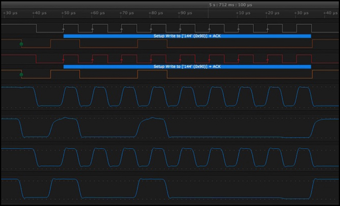
If you're curious about the trace above, that's an Arduino talking I2C to a simple temperature sensor across a voltage-level conversion circuit, with traces from both sides of the converter captured by my Saleae logic probe. Which, by the way, is a really cool diagnostic tool. Why I2C with multiple voltage levels is important is something I'll get to later in this post.
I'm still thinking about and planning the next layout. Control systems are a big part of that, because I was never happy with the DCC-throttle control of turnouts I used on Sumida Crossing, and my attempt at a single big computer-driven system never got off the ground, and would have had some of the same issues if it did.
As you may have noticed, I've spent a lot of time looking at control bus systems over the last two years. I'm still on the fence about what to use, as I don't particularly like any of the current systems. LCC has promise, but so far that's all it has, and I'm not expecting much from it in the next couple of years; it's too new.
Now I won't need a whole lot of turnout controls. Japanese railroads are notoriously light on turnouts, due to their focus on simplicity and efficiency. A turnout you don't have, can't break and snarl traffic. Building parallel express and local lines is more efficient, with enough scale, than building stations with express tracks and platform sidings for locals. Although there are numerous exceptions.
The new layout's also going to use flex track, which means something other than the Kato switches I've been using. Some kind of switch motor, and a remotely-controllable switch motor controller, are in my future.
The Problem
One of the busiest stretches of Tōkyō's commuter system, in terms of both complexity and traffic, is one I want to model: the stretch of the Chūō line west of Akihabara. Here the Chūō-Sōbu line from Akihabara becomes the Chūō Local line, and the Chūō line from Tōkyō station becomes the Chūō Rapid line, with a mass of crossovers and underpasses in a short section of track parallel to the Kanda river. It's a busy line, both visually and in terms of operating complexity, and it curves with the river and descends a small hill at one point. I really like the visual appeal of it.
I think I can compress that section of a kilometer or so into a modelable-size space. It won't be the only scene on the new layout, but it's going to be a key one, featuring at least two passenger stations and a four-track line. If I can find a bit more space, I can go a bit further along the river and model another station or two, a small engineering depot, and a park with Sakura (cherry) trees.
It's also going to have three double crossovers plus a single crossover and, if I include the engineering depot several additional switches. The crossovers probably won't be used often. They appear to exist mainly so that both tracks of the rapid line can be used in the same direction at peak periods. And the depot will be mainly for scenic appeal. Still, I may want to operate through a rush-hour, and that means throwing the turnouts between trains. I want some way to do that from in front of the layout, without punching cryptic three-digit codes into my throttle. But I eventually also want central oversight and possibly a dispatcher, which means simple switches or ground throws aren't the solution.
So I need fascia controls for the turnouts, and something to manage the associated signals. The turnouts themselves will be motorized, and have signals, which I want to work prototypically. Each set of turnouts and signals, an "interlocking" in railroad terms, can be managed independently, which keeps things small and simple. And I need to provide for some way to add a control bus in the future even if I don't have one at first. I also want block occupancy detectors, at least long term, so I'll need controllers for those too.
Good Ideas and False Trails
My first idea was some kind of control bus with commercial controllers. I've really been thinking about that for a couple of years now, hence all my interest in control bus systems. But as I said, I don't find any of the current offerings really appealing. Any of them could be the solution, but none of them grab me and say "this is it!".
Back in March I posted about using an Arduino as a signal driver via charlieplexing, and in April I posted about servos. Unlike the signals library I never finished the servo library, although it's mostly working. I need to clean that up and get it published.
I think that the two of these will work well for my small interlockings. But a cheap Arduino doesn't have enough pins to do much. I could buy the Mega 2650. I'm starting to see cheaper versions of that now, and it has a lot of pins. But the CPU runs at the same speed, and the memory isn't a whole lot larger. And even the Mega doesn't have enough pins for some things I might do. It's not an ideal solution, particularly if I need to scale up for a large yard complex, and I do plan one, perhaps based on the Tabata depot.
I'm not the first person to think of using Arduino this way. Many people have tried to do prototypical "control point" systems using Arduino, and I know of only one that even partially succeeded. It's a much harder problem than it looks, and you quickly run out of pins and/or processing time with just one Arduino. But a small distributed system of them, that could work. I just needed a way to interconnect the Arduinos.
So that's when I hit on the idea of tying a set of Arduinos together with a simple serial bus. Not a full-bore control bus, but just something simple for a short section of track to manage one or two closely-spaced interlockings connected to fascia-mounted controls.
At this point I should note that the Arduinos I'm talking about are the Pro Mini, which is selling for under US$10 now. So a cluster of these won't be very expensive. It's probably going to end up cheaper than my old DCC solution, and a lot more capable.
I spent a couple of months over the summer working on an idea for multiple Arduinos linked via a serial bus, that ultimately dead-ended, although it left me with some software I can modify and re-use, so it wasn't wasted time. In the fall I spent some time chasing LCC before I decided that it wasn't mature enough for this project, although I may revisit that later. So now I'm thinking the serial bus idea is still a good one, I just went at it wrong the first time.
Additional Requirements
While all this was percolating in the back of my head last Spring, I spent some time studying prototype signal systems and Centralized Train Control (CTC). Part of my interest in this comes from the fact that the Chūō line was one of Japan's first CTC installations, and CTC is still used as a component of their more sophisticated modern control systems. I also find reading old technical documents an interesting pastime, and there are a bunch of those available online as well as a couple I had to buy used. For some information on Japanese use of CTC, see my Signaling page, and for additional reading see the References at the bottom of that page.
One idea I had, when I was still back on the "control bus" plan, was to use JMRI with a control panel for the whole layout. I hadn't thought about CTC back then, but JMRI actually has fairly good support for CTC control panels and with scripts I could implement the necessary interlocking logic to go with that.
Someday I still want to get there and have JMRI provide a dispatcher control panel, and maybe I'll do something with LocoNet initially; I have enough LocoNet hardware I can salvage from the old layout. But that's not my "day 1" plan, or at least I don't think so at present.
One big problem is that a control panel on the other side of the room doesn't really solve my "in front of the layout" problem, and if I build fascia controls that only work with the full JMRI-based dispatcher system, I'm probably going to have a bunch of non-working fascia controls for a very long time, since I probably won't build a dispatcher's panel until the track plan settles, and that may be well after I start construction.
But then I realized that I could do something more prototypical using the Arduinos I planned to use for the signals and turnouts. Write the actual interlocking logic in the signal and turnout Arduinos and have them respond to a subset of CTC-like commands, and use another Arduino as the switch/light controller sending those commands.
Basically the way CTC works is that the control panel sends simple "do this" commands to signals and turnouts, and logic at the destination evaluates the current positions of the turnouts, occupancy of the track, and settings of the signals to determine if the command is safe. If it is, it gets executed. If not it gets ignored and the operator has to figure out why and fix that. This keeps you from throwing a turnout under a moving train by accident, which seems like a nice feature to me. I'm quite capable of pushing the wrong button when I'm busy, and these models are fairly expensive. I'd rather not bang them and the scenery up.
My first attempt at that was what I did last summer, and it mainly failed because I tried to be too clever and homebrew a serial system, rather than using one that was right in front of me (that wasn't the only problem, but it was a big one).
At this point you may be shaking your head and asking "wouldn't JMRI and LocoNet be simpler?", and maybe they would. But that's something of an all-or-nothing solution, and my last attempt at it didn't go so well. And I definitely want to do things with Arduinos in the new system, and those don't interface to LocoNet very easily, one of the issues that started me looking at alternatives a couple of years ago.
Third Time's the Charm, Maybe
That all got pushed aside for most of the fall, by a combination of real life, my LCC investigations, and some more research on signals (I still need to write the last post for that series, on actual interlockings). A few weeks ago, I started ramping up for the Arduino project, trying to figure out what I needed to work on, and researching a few things.
The new serial solution is going to be based on I2C, a simple yet flexible serial bus designed for short-range applications at moderate speeds (typically around 100 Kbps or less over distances of a couple of meters). The Arduino has fairly good support for this built in, although I have some work to do there.
At this point, I've got a pair of Arduinos communicating with low enough overhead that I can make the charlieplexing work (I haven't actually tested that yet, but it's coming soon). But I've also discovered a couple of problems, and had some additional ideas.
Problem one is that I2C is designed for a central controller, and the Arduino implementation for that is a bit problematic. When the controller is sending data it can't do anything else for a millisecond or longer. It's hard to multi-task in something as simple as an Arduino with pauses that long. The problem is that master mode doesn't use interrupts, and there are numerous reports of problems with interrupts from people who tried to fix that. The other Arduinos just have to respond to the master, and those have fairly good interrupt support. It's not perfect, and I'll need to be careful mixing it with charlieplexing, but I'm fairly sure it will work.
Problem two is that it's pretty obvious that even if an Arduino could talk to my future control bus, it probably couldn't do that and simultaneously deal with I2C. That's just a bit too much, I think.
So the result is that I'm probably going to use a Raspberry Pi as the control-panel driver and I2C master. This way I can connect it to my future control bus. The Pi is a Linux system, so I'm sure there will eventually be some kind of support for whatever bus I choose. And it's a real multi-tasking computer, so I can write different programs for different things and run them at the same time, letting the operating system handle the multi-tasking. The Pi is a bit short on pins, but I can always add another Arduino just to read switches if I need to.
This led me to spend a number of weeks learning about the Raspberry Pi. I'd wanted to do that anyway, and this made for a good excuse. I haven't got the Pi talking to the Arduinos yet, but I have it talking I2C to a simple temperature sensor, so I know how to use the I2C library. I just need to write a pair of compatible test programs, wire up some circuits, and I'm fairly sure that will work.
Because the Pi operates on 3.3V and the Arduino on 5V, the I2C bus has to work across two different voltages. Now it turns out that it actually can do this without additional circuity, but a US$4 level-shifter can also be used, and this is cheap insurance against a wiring error blowing out my expensive (well, US$40) Pi. The temperature sensor was my test for that as well as learning basic library functions (it was cheap and runs on 3.3V also) and I got the Arduino to talk to it through the level-shifter just fine, so I’m beginning to feel like I know what I’m doing.
Next Steps
I'll eventually need to adapt the communications library I started last summer to work with I2C (and complete it, which is still a lot of work to be done), and there's a whole bunch of as-yet-unwritten CTC stuff to go atop that. But before all of that are probably a bunch more tests on smaller-scale stuff, getting more familiar with the hardware and software I'm using.
In particular, I need to investigate I2C some more, check out how well it works with a couple of meters of bus wire in electrically noisy environments, and get more familiarity with its I2C support.
I also need to do some more work on just what I'm using for fascia controls. Do I go with simple physical switches, model CTC controls, or maybe something a bit more complicated? More on that in another post.
Plus I need to finish the turnout-controller library, and also decide what I'm doing for occupancy detection, and write some code for that (library #3, I expect).
My intent is to work on all of these over the next year. Maybe somewhat in parallel. And I'm going to try to post intermediate "this is what I have so far" posts as I make progress on each, rather than waiting until I have one "done" (as if any of this is ever really done). That should both provide more posts, as well as motivate me to keep working. I've found in the past that having a self-imposed "I need to publish something" deadline is a good way to motivate myself to dedicate a few hours a night to project work, and that's how progress gets made. I’m not going to post every week, but at least once a month, and every 2-3 weeks would be even better.
I'm also going to try to make more progress on planning the next layout. So far I've really only settled on one major scene plus a yard, which may or may not be a scene itself. I'm going to need a bit more than that before I can rough-in a track plan and grab my tools.
So, 2016 should hopefully see a return to more frequent posts here, as well as some interesting developments, and probably some libraries that others can use for their own projects. We'll see how reality ends up matching up with those grandiose plans.