


Signals I: Development, Regulation and Use
For more than 150 years, signals beside the tracks have been used to provide guidance to the operators of trains. Originally this was a simple “stop” or “go” message, but over time it became more elaborate, and the signals themselves more complex. Today signals provide fairly detailed guidance that allows for efficient and safe operation. But how they do that varies a lot between railroads. Signals have also become specialized, with signals at stations, junctions and similar points (“interlocking signals”) behaving somewhat differently from signals along uninterrupted lengths of track that exist mainly to separate trains (“block signals”). There are also many other, more specialized, signals.
Signals used in Japan are both simpler than those used in many other places, and allow for some capabilities that others do not (or that they do using more complex methods). But they also have a lot in common with signals used elsewhere. That shouldn’t be a surprise, as Japanese practice originated, as did that of many other countries, in British practice of the late nineteenth and early twentieth centuries. However they were also influenced by North American practice (which itself originated from mid-to-late-nineteenth century British practice). And they created some things unique to themselves. But I think that to understand them, it helps to take a look at how signals are used on railways around the globe, particularly block signals, as Japan has streamlined their system by focusing on block functions.
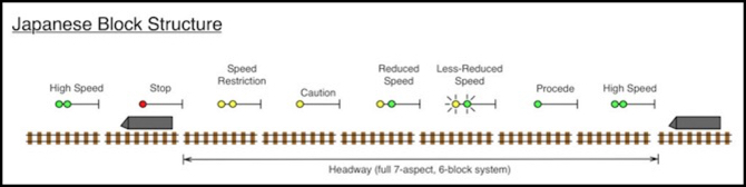
The diagram at the top of this post shows all of the possible signal indications used in Japan, laid out sequentially as they could be. In practice, I doubt any single railway line uses all of them together like this. Subsets are much more common. But a key part of their system is that there is a simple hierarchy (or rather a set of non-conflicting hierarchies) behind it. This is a bit of a tease, as I’m going to leave Japan and wander the globe for a bit in this post before I get back to explaining this diagram in a separate post. But I will include Japan in today’s discussion.
When I started writing, I was expecting this to be a standalone post; something fairly simple I could cover in one moderately long article. Even trying to keep myself focused to block signals, which are simpler than the signals found at interlockings, this turned out to be a lost cause and the details kept piling up. So instead I’m going to break up the material a bit, and cover background and some history today, leading into a survey of how modern block signals work around the globe as a second post. I’ll probably follow up with one or more posts related to interlocking signals later, but I haven’t thought as much on that aspect.
Today’s post, then, will focus on the role that signals play in general, and how that has evolved over time. The nature and relationship of “blocks” and “interlockings” will also be discussed, and how that affects the signaling system.
The Purpose of Signals
Let’s start with the basics: a signal is a device that keeps trains from running into each other. That’s rather obvious, but there’s a corollary that might not be so clear-cut: a signal is a device that lets trains get as close to each other as is possible without running into each other. That means that signals not only provide for safe operation of individual trains, but for efficient operation of railways with many trains.
Those two benefits of signals underlie every decision about how signaling systems are designed. But nothing comes for free. More complex signaling systems provide more safety and/or more efficiency (often both), but they come at a cost, both in capital (money spent periodically over the long term) and maintenance (ongoing support costs in money and labor). Railroading is a capital-intensive and often labor-intensive business, and railroads try to minimize both to remain profitable. Thus a decision has to be made about what the benefits of a more complex signaling system are worth.
And governments get involved, particularly when a signaling system (or something else) fails and two trains do run into each other. If people die, or other types of large-scale disasters take place, such as fires or chemical spills, there will be a strong push to “do something”, and that something is often to “fix” the signaling system so that it will prevent that event occurring again, even if it is relatively unlikely and the fix will be expensive.
That may seem unfair or inefficient, but it’s a fairly common approach. And it’s been applied to signaling for more than 175 years and we still have trains, and they’re a lot safer than they were in 1840, so it obviously works, even if nobody considers it optimal.
In the absence of forced change, the decisions made for a railroad carrying passengers with closely-spaced stations will be different from those made for one carrying long-distance freight. Since most railroads are a mix of those two functions, decisions will be compromises between sometimes-conflicting priorities, and resolving those conflicts is another reason governments get involved. Local history, and the decisions of governments based on that, can further modify what is perceived as the “optimal” system design. The end result is that no two railroads choose the same set of solutions.
Standards, typically imposed by governments on a national scale, do tend to harmonize things, but they often build in options to allow individual railroads to tailor things to their own needs. Moving trains around safely and efficiently has some fundamentals that don’t change all that much, which also provides a tendency for different railroads to make similar choices. Finally, modern practice around the world has evolved from a few early systems: the U.K., Germany, North America and Soviet-era Russia (and their manufacturers) all exported equipment and standards used across multiple countries, and even those who didn’t buy from them often imitated them.
The result is a surprising amount of commonality between different signaling systems when you dig into the details to see what is really going on. However the external form this takes can still be very different from one railroad to the next.
References and Sources
Signaling is a really complex topic. You could write a book about this. In fact, there are a number of them, not to mention a lot of specialized online sites catering to one specific railroad or multi-railroad signaling system. It’s also easy to misunderstand, particularly if you know one system and make assumptions based on that about how others work.
My modeling used to be focused on North American railroading of the late twentieth century, and that colored my understanding of the topic. We do things somewhat differently here from other parts of the globe, simply because we’ve been more focused on long-distance freight than passengers since the middle of the twentieth century. I’ve rewritten this post a couple of times in the process of writing it, simply because I found myself making assumptions that proved unfounded. There may still be mistakes of this sort I haven’t caught.
I’ve been doing a lot of reading on signaling over the past six months. Mostly this was digging more deeply into how the adoption of Centralized Train Control (CTC) and other systems, and the changing requirements of the late twentieth century, changed earlier practice. I’ve also gone back and re-read some things I’d read before with fresh eyes based on what I’ve learned since then.
I’ve long been a fan of Brian Solomon’s book Railroad Signaling (hardcover ISBN: 978-0760313602, paperback ISBN: 978-0760338810), which is a good treatment of the topic in readable language, although it does have a strong North American focus. But another book I discovered recently, Railway Operation and Control by Joern Pachl (paperback ISBN: 978-0-9719915-6-9) has a more balanced view covering current European practice and contrasting it with the North American approach and some of the underlying history (it also briefly touches on the Soviet influence on Eastern Europe and elsewhere).
See the references section at the bottom of my Prototype Signaling page for a list of some of the other sites I’ve used regarding Japanese signaling and its influences. In addition to the sources listed there, I’ll provide a list at the bottom of this post summarizing the more useful sites I used for the practices elsewhere, although I’ll note that it’s not a complete list. I didn’t keep notes on all of them, and this isn’t an academic paper.
And as usual, I’ll add the caveat that this is my hobby. I’m not a professional in this field, or any related field. Sometimes (often?) I get things wrong. Don’t take anything here as the unvarnished truth. I’m pretty sure I’m correct in all that I say here, and I’ve given it a lot of thought. But there may still be errors or misunderstandings.
Signal Use and History
It’s worth noting that signals are not universally used. Many lines, and even whole railroads, operate without any kind of signals even today. And others still use technology from the 1800’s, including wooden semaphore blades. Color-light signals became widespread in the 1920’s and 1930’s, as railroads experienced the last years of passenger-driven prosperity, before the war and the subsequent highway-building boom changed the industry forever. But they weren’t adopted everywhere. Today we’re in the middle of a new growth period as increased fuel costs and urban growth push people and cargo back to trains, and signals are being upgraded or installed in many places, and modern systems are displacing those near a century old, but they are still a long way from being universal, and places that never upgraded may still not have reason to upgrade today.
And color-light likely never will be universal, at least not in the sense of lineside masts with lights. New technology is already replacing lineside signal masts with signals displayed on a panel inside the train (called “cab signals”). This isn’t just for high-speed rail. Japan’s Yamanote line, a low-speed urban heavy-rail system similar to a subway system, except that it’s entirely above ground and has one grade crossing, runs entirely on cab signals and has no lineside signals (that’s also true of the Shinkansen outside of some specialized station signals). Europe’s ETCS system will ultimately eliminate lineside signals in favor of cab signals. And efforts in the U.S. for Positive Train Control (PTC) will likely eliminate any need for lineside signals. How quickly that will happen is unclear, but in the long run the lineside color-light signal will eventually be as much of an anachronism as the wooden semaphore.
Fortunately for those of us who like them, they’ll probably take a similar amount of time to disappear entirely. Or perhaps not. The UK is in the middle of a major change in their signaling practice, motivated in part by the high cost of updating post-war systems that have reached the end of their life. The result will be large-scale elimination of lineside signals. In the U.S., railroads are resistant to PTC and busy replacing similarly-aged incandescent-bulb color-light signals with new efficient LED (light-emitting diode) signals, but PTC may very well lead to a similar elimination here. Japan, always eager to be on the cutting edge, could follow suit (I believe they are already using LEDs, but haven’t seen much written about them).
History of Signals, Blocks and Interlockings
Signals were developed early on in the nineteenth century, although those signals looked nothing like the current ones. The earliest were used where two different railroads crossed, to clearly indicate who had the right of way. Gradually they spread to more uses, and their forms became the ones we are familiar with today.
Block systems existed before signals were used for blocks. The earliest forms are what were later called Manual Blocks. In these, a stretch of track between two stations (or other railroad offices) would have trains admitted to it though the cooperation of an operator at each end. This cooperation could be via telegraph, or some electrical system that just showed the operator a “block clear” or “block occupied” indicator at each end based on switches set by the operator at the other end. Often these were more elaborate, but the fundamental idea was that only one train could be in the block, and once one operator admitted a train in, the other would know not to do so. Once signals were developed, an operator could admit a train to a block by “clearing” the signal (making it not be showing a “Stop” aspect), but this was separate from the act of reserving the block for it. Once in a block, a train would run until it reached the far end and was admitted to the next block (or a station or similar), and only then would either signal operator be allowed to admit a train to the first block.
This approach had limited capacity, and long lines between interlockings would need block offices along the track for no other purpose but to admit trains to the next section if the railroad wanted to make better use of the track. Since that usually wasn’t practical, there were ways to send multiple trains after each other that were sometimes used, but these could result in accidents. Blocks weren’t the only method in use either, but they were fairly efficient compared to the alternatives.
And to be fair, a well-managed manual block system works very well with short blocks and closely-spaced stations. The U.K. continues to make use of such a system, although they call theirs Automatic Block, which is very different from what North American railroads mean by the same phrase. I’m going to use the phrase “automatic block” to mean a block whose signals operate with little or no human intervention. That’s the North American use of the phrase, and is also used in translations of Japanese descriptions of their system. And in my opinion it’s a more obvious meaning. But keep in mind that others use those words differently.
When the track circuit was invented in the late 1800’s, using electricity to detect a train on a section of track, it became possible for block signals to operate without a human. This allowed block stations to exist without an operator present, making the division of longer lines into more blocks possible. This substantially increased capacity on some lines. These signals partway along a line between stations are sometimes called “intermediate block signals”, but often that’s simplified to just “block signals”.
Early automatic signals were electromechanical (mechanical linkages controlled by motors or electromagnets) or electropneumatic (pressurized lines controlled by electric pumps or valves). These signals used moving blades (semaphores). At night, colored lenses on the blades would move in front of a kerosene lantern to produce a color-light signal that could be seen from a greater distance. So these still needed a human to come by and hang the lanterns every evening. By the early 1900’s electric lamps were used with these, and by the 1920’s these became bright enough to completely replace semaphore blades for daytime use.
At the same time, relay technology for controlling signals was becoming more complex. Early automatic block signals existed by 1900, and were elaborated in the early decades of the twentieth century. The Automatic Permissive Block system (APB), invented in 1913, still underlies much of modern North American block signaling, although current systems have gone beyond it (other countries have imported the technology or developed similar systems).
Aside from industry sidings and places where trains could pass each other on single-track lines (passing sidings), turnouts (track switches) tended to be clustered at stations or yards, where one person could oversee their use. Early on this led to the idea that signals and turnouts could be mechanically “interlocked” so that one could not be changed if it conflicted with the other. And from that, these clusters eventually came to be known as interlockings.
The use of a two-story tower that provided an interlocking operator with a view above the roofs of passing trains became common in both North American and U.K. practice (and elsewhere; Japan has them). These persisted into the modern era, with mechanical interlocking equipment replaced first by electrical relays and later by computers. From these came other ways of referring to an interlocking, such as “towers” or “cabins”. Another term, deriving from the use of Centralized Traffic Control (CTC) is a “Control Point”, although that is also applied to places that traditionally would not have had an operator but can now be controlled via CTC. But by any name, the function of an interlocking hasn’t materially changed in over 150 years; it’s just the technology, and the degree of safety provided by that technology, that’s improved.
A modern railroad can be considered as a collection of interlockings separated by blocks. Interlockings can be simple, like the two ends of a passing siding on a single-track line, with the whole one interlocking or with the main line and siding treated as a pair of independent blocks between them. Or they can be as complex as a major passenger station, with dozens to hundreds of switches and signals (some manual interlocking towers had as many as 200 levers to control individual signals and switches).
Rules, Laws and Standards
In general, railways make their own rules of operation, although they have to follow applicable laws and there may be standards that are used by more than one railroad in a geographic region, either informal because they buy from the same suppliers or formal because they’ve chosen to conform to some defined common practice.
Laws can be fairly general, such as a requirement not to block a grade crossing for longer than a set time, or to operate trains “in a safe manner”. But over time, as railroads had accidents due to neglect of their own rules and standards, or even simply for unforeseen reasons, lawmakers gradually became more involved and more strictly regulated the operation of railroads, often dictating specific operating rules.
In the United States, there had been various state regulations and obligations imposed by railroad charters, but the Federal government took over in 1887 with the creation of the Interstate Commerce Commission (ICC). Although initially focused on rate-setting (the stimulus for its creation had been the perception of unfair business practices by the railroads) its authority was soon (1893) extended to railway safety regulation. In the later part of the twentieth century most of its regulatory powers were removed by “deregulation” of the railroads, or separated off to other agencies, and the ICC eliminated in 1995. Much of what was left of the ICC’s powers ended up in the newly-formed Surface Transportation Board (STB). However the Federal Railroad Administration (FRA), created in 1966, is responsible for railroad safety regulation, among other duties.
Standards were often developed by a single railroad, or a railroad working in conjunction with one or more manufacturers. But various standard-making bodies soon arose. In North America (including Canada and Mexico), this began in 1872 with a meeting of some railroad managers to establish Time Table Conventions. In 1892 this group took on the name American Railway Association (ARA), and later absorbed other similar groups. In 1934 it merged into the Association of American Railroads (AAR), which included other trade groups, mostly focused on the business of running railroads (as opposed to the technology of doing so). The AAR’s focus was more strictly North American (Mexico isn’t mentioned in the description). In 1997 the Communications and Signal Division of the AAR was removed and added to the newly-formed American Railway Engineering and Maintenance-of-Way Association (AREMA), which was more focused on standards-making for railroad infrastructure.
Other countries took other paths. I don’t know the history of Japan’s evolution, but today the Ministry of Land, Infrastructure, Transport and Tourism (commonly abbreviated MLIT in English documents) contains a Railway Bureau that publishes a “Technical Regulatory Standard on (or for) Railway” that defines national standards for many different aspects of railway technology and operation. There is also a related “Approved Model Specification” that goes into more detail on what the bureau considers to be equipment that meets the requirements of the standard. This is available in English translation from the MLIT (see references at end). These are written fairly broadly, with lots of room for individual railroads to choose subsets or apply different parts of the standard based on local needs.
But the end result is largely the same: some degree of autonomy under country or region-specific laws that can be fairly detailed, and using technology that is standardized across one or more railroads within a geographic region. All of these groups are, obviously, aware of what other such groups have done and are doing (there are international conferences on different aspects of railway technology), but they have different histories and priorities, so the exact solutions reached vary between them. For signaling, the end result is that practices differ fairly substantially around the world, even while holding some core similarities.
Aspects, Indications and Color-Light Signals
Modern signals are often some form of electrically-operated lights with different colors, called a color-light system. Other methods exist, such as the PRRs famous position-light signals. They’re not the only railroad to use lights to mimic the position of a semaphore signal’s blades, either, many European systems have signals where the meaning depends on angled lines of lights. And in the twenty-first century, digital electronics has made possible the use of numeric displays, such as for showing explicit speed limits. But collections of lights where the color matters are the predominante form of railroad signals around the world, so I’ll use those in the examples here as a generic shorthand, rather than trying to draw exactly all the different details of display. What I’m after is illustrating the meaning, not the method.
The form of the signal and how it is used is called the “aspect”, while the meaning this imparts is called the “indication”. Whether it is a color light showing yellow, or a string of lights inclined at 45-degrees (or even a wooden blade at 45-degrees), the usual meaning is “be prepared for the next signal to be red”. That indication is usually given a short form name, such as “Caution” in the U.K. and many other places, or “Approach” in North America (and some other places).
As an aside: “caution” is also often used informally in North America in addition to “approach”, and was even found in older standards documents, but appears to have been replaced by “approach” in current formal documents.
Aspects vary considerably between railroads, while indications are actually more likely to be similar. This is because there are a limited number of indications required and those derive from the handling characteristics of trains, which don’t vary a lot from country to country, much less between railroads of the same country. But even with all the variation in aspects, today the most basic colors and their meanings are nearly universal.
Aspects have evolved separately in many places, although you can trace lines of influence in their similarities. Japanese signals derive in large part from British influences, as do many other aspects of Japanese railroading, although American practice has also had some effect. But the modern Japanese and British systems are quite different.
The three fundamental aspects of modern color-light signals, which are nearly universal, and their indications are:
- Green: “Proceed” or “Clear”, allowing operation at the maximum allowed speed
- Yellow: “Caution” or “Approach”, warning to begin braking for an upcoming red signal
- Red: “Danger” or “Stop”, prohibiting a train from passing the signal (usually)
As we’ll see below, a red signal has absolute and permissive signal variations, so “Stop” doesn’t always mean “Stop Now”. Some U.S. railroads in mountainous areas also allow heavy freight trains to pass red permissive signals at low speed without stopping, because restarting a heavy train on a steep grade can be impractical. And permissive signals allow a stopped train to resume moving past the red signal with some restrictions. But both of these usages carry an obligation to be able to stop the train short of any obstruction in visual range, so while relaxed, the meaning is still “be prepared to stop immediately”.
But this is only the basic set. And as we’ll see, some railroads make their signals much more complex.
Speed and Route Signaling
One complexity comes from the fact that signal systems are often divided into those that describe behavior in terms of speed (called “speed signaling”, obviously enough) and those that provide information on upcoming changes in direction (called “route signaling”). Both of these require additional aspects to convey the information, at least usually.
This addition primarily affects the aspects and indications used at interlockings, and usually block signals aren’t directly affected. An exception exists where a passing siding is part of a block. And sometimes signals near the end of a block take on aspects that depend on conditions within the interlocking. And finally, speed is related to braking distance, which affects block signal spacing, so blocks may make use of some or all of these additional aspects to allow more closely-spaced signals where that is needed for efficient operation.
Route signaling calls on the operator of the train to remember the specific restrictions for each switch on a line (which isn’t too hard as most will have the same characteristics). Speed signaling systems are slightly more common today, simply because they provide less room for human error (a given aspect always means the same speed). Speeds can also be described by fixed sign plates, where separate signals for a route exist, or in more modern systems by digital displays attached to a signal mast. This latter approach is more common in Europe than elsewhere (it is permitted in Japan, but I’ve never seen an example of it in use). And even in route-signaled systems, some aspects may have associated speeds defined (North America’s BNSF uses this kind of system).
When speeds are described via aspects, there are two that nearly every railroad has in common: Medium, which usually means something around 50 kph (30 mph) and Restricted, which usually means something around 25 kph (15 mph). The former is the speed at which a train can go through a typical mainline switch. The latter is the maximum safe speed for stopping short of an unforeseen obstruction within visual range, such as a broken rail, but also applies to sharply-diverging switches. Many railroads have other important speeds. A fairly common one is Limited speed, which is usually in the range of 60 - 75 kph (or about 40 - 50 mph). Limited speed is sometimes related to the maximum speed through a high-speed turnout at an interlocking, but in blocks, where there are no turnouts, it also relates to braking distance and block spacing. The exact meaning of a speed name will vary by railroad, and sometimes by class of train (passenger trains typically being allowed to go faster, since they can brake more effectively than freights).
Japan uses a speed signaling system where light colors define speeds and routing information is provided either via multiple heads on one mast, or via additional markers or alphanumeric displays. So it is usually described as a “hybrid” system with elements of both types. For detail on that, see my Japanese Signaling pages.
Blocks and Interlockings
As I said earlier, a railroad can be thought of as a collection of simple tracks without branches or junctions, managed as “blocks”, plus a number of places where trains may originate, terminate, or take one of a choice of routes. The latter also include simple crossings where two railroads cross without a connection, as well as more complex junctions. Collectively all of these places that are not blocks are called “interlockings”, because their control systems require that signals and turnouts be “interlocked” so that authority to pass a signal can only be given when the route is not in conflict with some other active route, and that once given authority cannot be taken away (until the train passes or some other mechanism is used to safely annul the authority).
Signals play a key role in both systems. In blocks, they admit trains to blocks and to sub-divisions of blocks (often called block sections). At interlockings they provide not only authority to move, but additional information on route and/or speed. And for both they provide warning of conditions beyond the visibility of the train’s operator (engineer or driver).
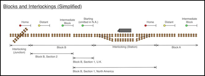
The following diagram shows a very simplified overview of two interlockings and a pair of blocks. In this diagram only one direction of signals is shown, for trains moving from right to left. On a real railroad, there would either be two tracks, each with signals for one direction, or there would be one or more tracks but with two sets of signals per track, allowing trains to move in either direction. Following the usual convention, the base of the signal mast is placed where the block begins on the track diagram.
Additionally, in this and the following diagrams I’m simplifying the appearance of signals by showing common colors and color combinations, not necessarily those used on any specific railroad. Where two colors are shown above one another that could occur on two separate “heads” (sets of lamps with one background) or by lighting two lamps on one head, depending on the railroad. Railroads have many ways to convey the same meanings.
Block B is subdivided into two sections, the one to the left of the Intermediate block signal (up to the home signal of the junction) and the one to the right of the intermediate signal. In North American usage, the “block” would normally extend all the way to the home signal to the right of the station (this is simplified, and there are exceptions). In British usage, and in many other railroads around the world, there will be a separate starting signal admitting trains to the block, and thus the right section of block B runs from the starting signal to the intermediate block signal.
Note: strictly speaking, even in North America the area between two opposing home signals (the interlocking proper) is not part of any block. However authority to enter the departure block is given by the home signal entering the interlocking, so in a sense that block temporarily extends through the interlocking for that one train (a different block may extend through it for the next if there is a choice of exit routes).
The real complexity comes from all the different ways trains may share blocks and interlockings, and all the different kinds of advance notice that need to be provided to their operators. I’ll dig into the different kinds and usages of block signals in my next post. But for now, I’ll provide an overview of some basic forms of block signaling that were in use in the early part of the twentieth century, and in some places remain in use today.
The Interlocking
While I’m going to focus initially on blocks, I can’t entirely get away from talking about interlockings, because the two are intertwined. Modern block signals rarely exist in perfect isolation from interlockings.
Note that the terms “interlocking” and “station” mean different things. A station may be an interlocking, but small stations are often just a place in the middle of a block, with no local staff or signal control, and no sidings to be interlocked. And while an interlocking could be a larger station (or part of a really big one), it could also be a junction between two lines (of the same or different railroads), or the entrance to a yard or depot. With CTC, sometimes even a simple passing siding is treated as an interlocking, or even as two separate interlockings, one at each end.
Blocks begin and end at Interlockings (or at the end of track, but usually that will be within an interlocking). Interlockings have “Home” signals (the last signal before the place where tracks converge, diverge or cross) and often also “Distant” signals one out from the home signal. They may also have “Starting Signals” leading into blocks. Within an interlocking there may be intermediate signals (sometimes also called Home signals). The Home and Starting signals are usually “controlled”, meaning that they would default to a “Stop” aspect unless a human set them otherwise. Distant signals may be controlled or automatic (and this varies considerably between railroads), but they may also be nothing more than the last block signal before the interlocking, connected to and deriving their aspect from signals and occupancy detectors within the interlocking. Signals outward of the Distant signal may be automatic, but still take on aspects that depend on the state of the interlocking in a similar manner. The dividing line between block and interlocking is no longer as abrupt as it once was.
In typical North American usage, the Home Signal at an interlocking is also the signal controlling entrance to the block beyond the interlocking. In fact, the definition of Home Signal used by the Association of American Railroads (AAR) is “A fixed signal at the entrance of a route or block to govern trains entering and using that route or block”, despite the physical signal actually being at the entrance to the interlocking. Contrast this with the typical U.K. practice, where the Home Signal admits a train to the interlocking, and a Starting Signal is usually present to pass it from the interlocking to a block. Japanese practice appears to follow the U.K. in this regard (as do most other railroads around the world), which shouldn’t be a surprise given how influential British railway engineers were in the early days of Japanese railroading. However, starting signals are optional in Japan, and may be omitted in favor of a block signal at the exit of the station (the distinction seems to lie in local control; if there’s a stationmaster who can set the signal to release a train, it’s a starting signal leading to the next block signal, if not then it’s a block signal).
However, North American systems have used starting signals in some more complex stations, and in particular they were a feature of older manual block systems, where they admitted a train from a more complex station into the block or could be used in conjunction with distant and block home signals to hold multiple trains at a passing point mid-block). However, these were often called “advance” signals, a term that has a meaning distinct from a starting signal in U.K. practice (they are called “advance signals” because they are “in advance of” the home signal, where “in advance of” is a railroad term that means “beyond” even though it sounds like it ought to mean “before”).
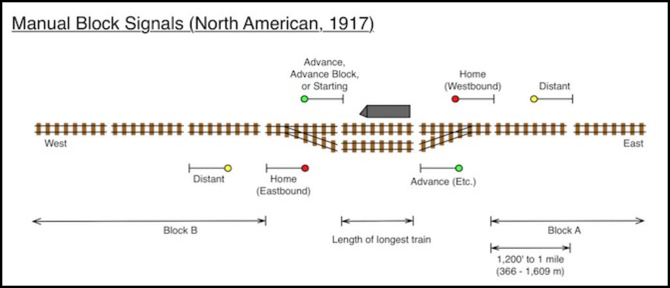
In the diagram above, the upper-left advance signal holds a westbound train to await another that will use the passing siding. While this could be an eastbound train, the top-right distant signal can be used to pass a second westbound train out of block A at a reduced speed (making block A free for the next train to start) so that it can use the siding to pass the held train. And then once it clears block B some time later, the held train can finally be released. Additional signals could be used for more detailed control over which route (main or siding) is used in each direction.
In the U.K. an “advance” signal could be either an “advance home signal” or an “advance starting signal” (the former sometimes simply called an “advance signal”). An advance home signal provided access to a second length of track within a station or other interlocking (e.g., for holding a second train within a busy interlocking). I’ll admit I’m a bit unclear on how that differs from an advance starting signal, but I suspect it has something to do with the specific authority granted by the two signals. In British terminology the distant signal is a “warning signal” because it cannot give a Stop (red) indication, but only provides a Caution (yellow) if the home signal is red. The others are different types of “Stop” signals because they can give a Stop (red) indication.
In Japanese practice, although the signals are under human control (or at least allow for that), Home and Starting signals mostly follow the same rules for allowed aspects as Block signals, but that isn’t always the case on other railways. It does simplify the study of Japanese signals though. And even in Japan, Article 101 notes that “The main track in the station and halt may not be a block section”, so they aren’t strictly the same kinds of signal.
That’s usually true elsewhere also. Signals within an interlocking may behave somewhat like block signals, but tracks in an interlocking aren’t part of a block.
Distant Signals
This is another term that means different things to different people. In many systems, particularly British-derived ones, a Distant signal is a signal that is associated with a Home signal, placed at braking distance outward of it, and capable of only (or usually) showing Clear or Caution, but not stop. With short blocks, sometimes the distant signal will be placed as a second head below the head of a normal block signal. This originated with British signaling, and is still common there. In North America it was typical of manual block systems in the early part of the twentieth century, but the use of separate signals tied to the home signal seems to have been largely replaced by block signals that are aware of the home signal’s state. Subordinate heads on North American signals mean something else.
The label can also be applied to a controlled signal that normally follows the Home signal as above, but can be forced to Stop, to hold a train away from an interlocking. Finally, the term also seems to sometimes be applied to the last block signal before an interlocking, which will be red if its block is occupied, and yellow if the home signal is red, but otherwise defaults to green.
In the U.S., where unsignaled lines are fairly common, an unsignaled line approaching an interlocking may have a distant signal in addition to the home signal at the interlocking, to ensure that trains begin braking in time (or are aware of a train ahead of them waiting to enter the interlocking).
Advance or Stating Signals
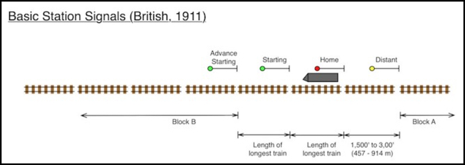
These names also come with several meanings. In North American manual block practice, the two names often mean the same thing: a signal following the Home signal at a station that controls admission into the next block (separating the functions of admitting trains into the station from that of admitting them into a block). In the U.K., there are usually two distinct signals
Blocks and Block Signaling
So a block is the track between interlockings. But what does that really mean? And what do block signals have to do?
A block is any section of a railway line that can be occupied by only one train at a time. Well, normally. There are exceptions like permissive signal rules that allow a second train in under very special circumstances. A block can be as short as a train, although usually they’re a mile or more (a couple of km) in length at a minimum. Or a block can be as long as hundreds of miles (km), but normally really long blocks will be broken up somehow for reasons of efficient use.
These subdivisions may use staffed stations, in which case each length of track between stations is treated as an independent block. But more commonly one long block is subdivided into “block sections” that can be independently occupied, and some of these may provide parallel lengths of track allowing two trains to pass.
A block is differentiated from non-linear sections of track where trains can originate, terminate, or change direction. Such places include yards, depots, large industry sidings, and (sometimes) tracks used for passing other trains. A block is also differentiated from complex track work at stations and junctions, although tracks within a station or junction may function as part of a block system (or may not, this varies by railroad).
A block can be part of a double-track line where each track is used only for one direction (“uni-directional track”) or it may be used (at different times) by trains running in both directions (“bi-directional track”). With double-track, each track has its own block, although they may have their boundaries at the same places and be numbered similarly (e.g., “track 1, block four” and “track 2, block four” could begin and end at the same locations, but functionally they are two independent blocks because a train on track 1 can’t affect or be affected by the operation of a train on track 2).
A long block can be divided up into “block sections”, which modifies the definition slightly: now a block can contain multiple trains, but a block section is exclusive to one. Trains moving in the same direction can follow each other as long as they remain in separate sections (with some consideration for spacing that we’ll get to below).
With sections, blocks signaled for bi-directional use can even contain two trains moving in opposite directions, although these are handled more restrictively than following trains. When moving in opposing directions there must be some provision made for them to pass each other at a station or siding, often this somewhere near the middle of the block; typically a “meet” between two opposing trains is planned in advance and the train that arrives first is required to wait for the other. With Centralized Traffic Control, meets can be arranged more flexibly, but this assumes some degree of visibility and control of at least some of the block signals by the CTC operator (or at least the creation of a “control point” at each possible passing location).
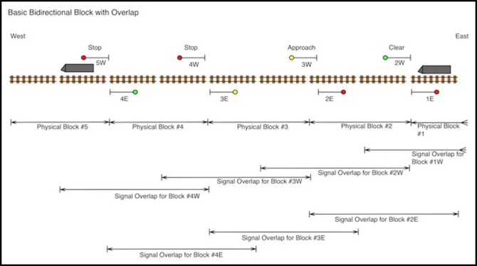
With signals, there will be a block signal admitting trains into the end (at both ends if signaled for bi-directional use). The track physically between successive signals is typically thought of as “the block” (or block section), and that’s a correct definition for someone operating a train. However, signals are linked to detectors that tell if trains are in a block, and often the status of the block depends on detectors that extend some distance into the next block. This is called “overlap”, and it is done to reduce the risk if a train overruns a red signal. With overlap, a train can’t be admitted into the block until not only that block is clear, but the adjacent portion of the next one is also.
Not all railroads use overlap, and it’s more common on passenger-heavy lines (it’s essentially a safety feature). For most of this post I’ll assume overlap doesn’t exist (blocks end electrically where they end physically). But it’s worth explaining just how it affects signal use.
The following diagram shows how signal overlap works with a bi-directionally signaled block composed of at least five sections. The train at left, occupying block 5 physically, will cause both block five’s signals and signal 4W (for westbound signal #4) to go to Stop. This is because it is close enough to block four that it occupies the portion of block five within block four’s overlap. Similarly the train at right occupied block 1, but is causing signal 2E to also go red because it is in the overlap for that signal.
Overlap can extend to an entire block (i.e., a train anywhere in block 5 will cause 4W to remain at Stop), and this is done on some rapid transit systems, but more commonly the overlap extends for the emergency-braking distance of a train, which is less than the length of a block (e.g., a train at full speed applying emergency braking as soon as it sees a red signal will stop after passing the signal but before reaching the end of the overlap). When braking distances are longer than a block, as they are in some multi-aspect signaling systems, overlap is less useful, but variations could still be used.
The above diagram shows a simplified Absolute Block system where signals are cleared (green in both directions) unless a block is occupied by a train. Such systems exist, but in present-day use are mainly for uni-directional track. In modern block systems, there is a concept of direction of traffic, and when the block is in use for trains moving westward as shown here, the opposing (eastward) signals would all be forced to Stop (red).
Absolute and Permissive Signals
A signal is said to be “absolute” if a “Stop” indication on it requires a train to remain stationary until the signal changes, and “Permissive” if the train may begin moving (usually at a very limited speed) after stopping. Signals controlling entry into an interlocking (e.g., a station or junction) are universally absolute signals, because of the potential for other trains to arrive from the opposite direction or from the side.
Within a block, intermediate block signals may be permissive when a line is used unidirectionally (or if it’s bi-directional but there are other systems preventing opposing trains from being within the section of line between two interlockings). Whether or not they are is a choice made by the individual railway (which may be restricted by government regulations). Permissive signaling reduces the effects of signal failures on efficiency, but adds some risk. The Pennsylvania Railroad used permissive signals, but only for freight and with a restriction that a freight train could not enter a block section occupied by a passenger train. Similar limitations may be in place by other users of permissive signals, or not.
Some railroads use distinct sets of lights for Permissive Stop and Absolute Stop, to allow for more precise control and reduce the risk of mistakes. But often the difference is based on some fixed characteristic of the signal mast, such a sign on the mast, or having lights staggered on both sides of the mast. Even in the case where the physical form denotes the nature of the signal, as noted above the “permissive” rule may only apply to specific trains or types of trains.
Permissive signals sometimes allow a train to pass a red signal without coming to a stop. This is needed in mountain railroads, where restarting a heavy train on a grade may not be practical. This is used even with modern roller-bearing freight cars, but was even more of an issue with older friction bearings. This kind of permissive signal is used on both western U.S. railroads and apparently some Russian railroads.
Automatic Blocks
A basic automatic block operates the block signals entirely automatically. Signals will be Clear (green) until a train enters, and then signals in nearby blocks will take on more restrictive indications to protect the train, but do nothing to prevent another train from entering the block from either end at a suitable distance. This approach can only be used if a block is unidirectional, or if some other method limits occupancy (e.g., agreement between operators of interlockings at the two ends, and some form on authority issued to the operator of the train). In North America this specific form is called simply Automatic Block Signaling (ABS), but that term is confusingly also used generically for other kinds of automatic blocks, and in other countries to describe local systems. In the U.K., the same phrase is used to describe a block with electrical admission controls, which may have manually-operated signals.
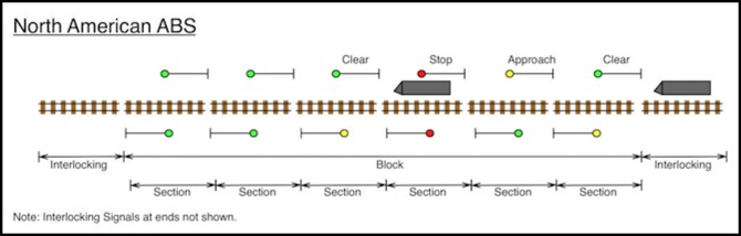
In the above diagram, note how only signals adjacent to the occupied block are affected. This simplifies the wiring needed, which is one reason such systems remain in use today. Also, the lower-right signal is yellow because it is tied into the interlocking, so the train there causes the signal for entry to the interlocking, which isn’t shown, to be red (actually, that’s the default for most home signals at interlocking, although I’m ignoring that detail here).
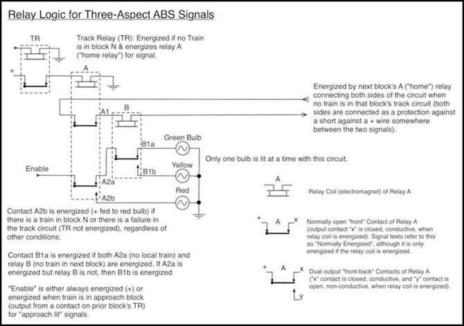
To make this work, each signal head needs just two relays (plus one for the track circuit). These connect to the next block ahead using two wires. There’s no end-to-end control circuit. Each signal is essentially autonomous except that it makes the “Green or Yellow” choice depending on the state of the next block’s track circuit (red will be forced if there is a train in the local block). In modern systems relays have been replaced with semiconductors or computer software, but these systems are still designed to use compatible voltages between signals, so older signals with boxes of relays next to them can exist on the same line as newer ones that are computer-controlled. And many relay-based signals are still in use.
In the following diagram, the track circuit of the protected block (block N) controls relay A for the signal admitted a train into the block. This diagram is drawn following a typical convention where the contact (the horizontal line with a pivot at one end) is presumed to be held in the “up” position when its associated electromagnet coil has power applied (“is energized”). The top (or “front”) output of the contact is thus energized when both its own input is energized and the associated coil is energized. When the coil is off, the contact falls down due to gravity (or a spring) and the bottom (or “back”) contact becomes energized (again only if its own input was energized).
The relay controlled by the local track circuit’s relay (relay A) is called the “Home Relay”. If this relay is energized, that means that there is no train in block N and block N’s track circuit is working properly, and it is safe to make the signal a color other than red. Contact A2a becomes energized (or rather is connected to “Enable”, which may optionally be de-energized if there is no train in block N-1, making the signals dark until a train approaches the signal). If A2a is energized, then the choice of Green or Yellow depends on the state of relay B (also called the “Distant Relay”). This will be energized if block N+1’s Home Relay was energized, meaning that there was no train in block N+1. If B1a is energized, the local signal is green. If B1b is instead energized, then there is a train in block N+1 (but not in block N) and the local signal will be yellow.
Note: the A1 contact isn’t strictly necessary, since the input to contact B1 is from A2a, which is only energized when A1 is also energized (both depend on coil A). But the diagram I used as reference was drawn this way. I expect this is a redundancy against some kind of short, but it could be omitted. Also, both the positive (top) and negative (lower) line from block N+1 will be connected to separate contacts on that signal’s Home Relay, to prevent a short against either wire from accidentally energizing relay B. This is a “fail safe” measure designed to prevent dangerous signal aspects from being displayed.
I’m not going to show relay designs for more complex signals, as these get complicated fast. See the Introduction to North American Railway Signaling book in the references section if you want to know more about how relays are used.
A somewhat more sophisticated method allows trains to enter from either end, but once one does the entry of a train from the other end is prevented. The North American Automatic Permissive Block (APB) system is an example. In this system, block signals are Clear (green) until the first train enters. Then all opposing signals to the far end of the block turn red and remain red until the train leaves the block. Signals for the direction in which the train is moving remain green ahead of it, and behind it take on protective aspects based on distance from the train, eventually becoming Clear. This allows a second train moving in the same direction to follow the first (at a safe distance), similarly to ABS. But trains from the other direction will be prevented from entering by the signals, unlike simple ABS) until all trains have left the block.
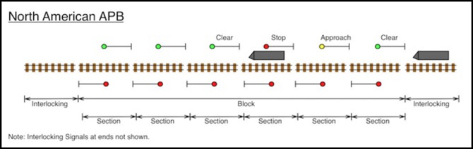
APB can be elaborated, and often is. One basic change is allowing opposing signals to clear behind the first train, unless a second enters. This allows a train in a mid-block passing siding to come out and continue moving once the first train passes but before it exits the block, as long as another train hasn’t already followed the first in.
Both of these are fully automatic systems, controlled using simple relays and track detection circuits without human intervention. But the basic idea of APB can be extended to a controlled system. With this, the operator at an interlocking (or at a remote centralized control panel) sets a signal controlling entrance into the block to Clear (green) from its default of Stop (red). In a CTC system this may be done as an effect of setting a “direction of traffic” for the block. Regardless of how it is achieved, this has the same effect as a train entering the block in APB, causing all opposing signals to go to Stop (red) except that this may remain in effect until the direction of traffic is cleared (leaving it set is sometimes referred to as “fleeting” as it allows a string of trains to follow each other into the block like a fleet of ships).
Modern systems use some variation of these two approaches, often the more complex controlled method. But which is used often depends on local operational requirements. And they may have been evolved independently of the North American methods, and have variations as a result.
These variations usually affect what cautionary indications signals can give. What’s shown here is a basic “three aspect” system (also called a “two block system, for reasons we’ll get to next time), without any duplication of aspects or other embellishments.
Summary
This post explained, I hope, how modern color-light signals evolved out of earlier systems, and how their usage became subdivided into block signals and interlocking signals, with different requirements for human intervention.
It also provided some basic material on blocks, including the ways in which block signals can automatically reflect conditions on a line without human intervention.
But it doesn’t cover how block signals have changed as trains became faster and heavier during the latter half of the twentieth century and the early parts of the twenty-first. That will have to wait for next time, when I’ll cover how blocks are used differently around the globe.
References
Japanese railway signals are standardized by the government’s Railway Bureau of the Ministry of Land, Infrastructure, Transport and Tourism (abbreviated MLIT). These are available in English translation online (PDF). Both the formerly government-owned Japan Rail (JR) railroads and the independent non-JR railroads appear to follow these standards, but they pick and choose the parts they want, so the actual signals and the aspects used will vary between railroads.
The 1942 edition of Edmund John Phillips’ Railroad Operation and Railway Signaling, which is available online via Google Books., provides an overview of the American Association of Railroads (AAR) standards that form a basis for most later North American practice (and to some extent this standard merely reflected existing practice on some railroads, while others continued to do things differently). This was relatively stable into the early post-war years based on other references I’ve seen, but individual railroads often diverged from these standards. Modern North American signaling still shows substantial influence from this standard, although there are now at least three separate types of standards in use (Eastern U.S., Western U.S. and Canadian), with both Eastern and Western U.S. (at least) showing further subdivisions between railroads.
The Pennsylvania Railroad was an influential standards-maker, not limited in scope to North America. They pioneered continuous cab signals (the U.K. had previously done cab signals that only updated when passing a signal mast) and a number of other things. An overview of their signals and how later successor railroads modified them can be found here. According to one paper (PDF), the PRR’s cab signals influenced a number of European systems (Hungary, Italy and Holland, to be specific), as well as Soviet Russia.
Early North American practice c. 1921 is documented in the Maintenance of Way Cyclopedia (PDF), including references to both manual and automatic block systems.
Current North American practice is mostly documented online, but the Institution of Railway Signal Engineers has an overview, which includes extensive discussion of the use of relays, in Introduction to North American Railway Signaling (Simmons Boardman, paperback, ISBN 0-911382-55-0).
For the U.K., a good summary is on Wikipedia, but you can also see the formal standard (PDF). Additionally, Indian railway signaling (derived from British practice), provides some perspective on how other systems derived their own practice based on the original British practice from the colonial period (and probably later; I doubt the influence ended with the end of British rule). Some early British practice c. 1911 can be found in The Railway Signal Dictionary (PDF), which contrasts them with similar U.S. practice at the time.
Australia provides another perspective, although apparently their systems vary quite a bit on a state by state basis (due both to historical development and type of railroading). I found New South Wales to be particularly interesting: for information on their signals, see this page.
The continent does things somewhat differently. For details of French signals (in English), see this page. For German practice (also in English), see here and here.
Interestingly, the U.K. has had a couple of experiments that weren’t adopted on a large scale locally, but which may have influenced others (or perhaps it’s just a case of parallel development). The LMS (London, Midland and Scottish) Railway tried a many-aspect block system around Mirfield junction in 1932, but it was only used on one other line. The Mirfield signals actually lasted until 1970. There was also a related system, apparently without the added block signals, but with fairly complex interlocking signals, used on ex-LMS lines in “North London” (the New Lines), which lasted with some changes up until 1988. Another interesting variation was made in support of “high speed” rail in the 1980’s (the InterCity 125’s, or HST trains), which added some additional signal aspects for testing (see discussion of the flashing yellow aspects here and here, the latter also has a nice discussion of other aspects of block signaling).
Russian signals are described here.