


Decoder Wars II - Lightboards
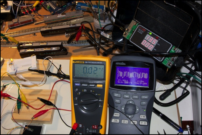
Yes, my workbench is a bit cluttered
Edit: there were a lot of typos in this post for some reason, all now fixed (I hope).
Comparing decoders for cab cars is actually relatively simple. These don’t need to do very much, so it’s really about checking basic functionality. I’ve laid out the full testing details on my Decoder Comparison Testing page, and here I’m going to summarize the findings for the capabilities of interest to me.
The ideal cab decoder supports:
- bipolar output for easy conversion of existing lightboards
- lights follow the throttle setting (one lead is + for forward, - for reverse)
- function for lights is F0 or mappable to F0
- a “rule 17” dim function that can be triggered by a function key
- rule 17 will or can be set to only affect the headlight
- function mapping for rule 17 (less important but I’d like to use F3 for all my trains)
- settable maximum brightness and dim output levels
- direction bit in CV29 works (and also applies to rule 17 lights)
- supports consisting, including direction bit in CV19
- consist function map (CV21/22); lights can follow consist or normal address
- clearing consist address does not clear consist function maps
- has a “decoder lock” feature
- RailComm would be nice, but I have no immediate plans for it
Let’s get RailComm out of the way: none of these have it (not even the Lenz decoder), and that’s not a problem for me.
Now I don’t have to have all of those features. In fact consisting is not going to be relevant to most of my trains, and I can live without “rule 17” lighting or with a minimal implementation of it. I can even live without remappable functions, although I’d really like to have all of my headlights on F0, so if a decoder defaults to another function (and some non-motor decoders do), then remapping is more important. I can also live without decoder locking, as I’m not likely to be making Ops Mode changes to anything other than consist addresses, which ought to apply to all of the decoders in a train anyway; an argument for NOT using locking.
I’d like to be able to read back CVs on the programming track, something I can’t do with my FL12-equipped Kato trains since the load provided by the lightboard is just too low. But again it’s not a make-or-break feature for me and as I’ll note below, somewhat impractical for a decoder manufacturer to actually do.
In short, it needs a direction-sensitive bipolar output that works well and I’d like Rule 17 support. Whatever decoder that fits in my trains and has that at the lowest price probably wins.
About “Rule 17” and Bipolar Decoder Outputs
The prototype railroad practice of dimming the headlight under certain circumstances is an old one, but its exact origin is unclear. In North American practice at least the Santa Fe referred to the section of their rulebook regarding headlight use as “Rule 17” quite some time ago. But in modern railroading it is commonplace, and known under a variety of rules. Every railroad rulebook is likely to have variations regardless of what they call it. The rules may require dimming the headlight when the train is stopped, or making it dark entirely. But in general the idea is to reduce intensity of the bright light any time someone close up may be looking towards the engine. This typically takes the form of rules requiring passing trains, as well as trains waiting on a siding, entering a station, or operating through a yard to run headlights at a reduced intensity. One railroad I knew required dimming headlights on a stretch of track that paralleled a highway.
As an aside, a locomotive may be required to operate headlights on both ends simultaneously (typical when switching in yards). Most small models aren’t wired to support this, and decoders tend to reflect that. A bipolar circuit ensures that headlights will only be on on the “front” end (and usually that tail lights will be lit on the other end, which itself isn’t necessarily correct practice if there’s something coupled behind the locomotive). If I were wiring a model from scratch, I’d want separate function outputs for head and tail lights, and I’d want them to be manually operated via a function, not automatically switched. But as I’m converting models with built-in lightboards I don’t want to rebuild, I want a bipolar output to drive the lightboard. And that has some implications for Rule 17 function use.
Decoder manufacturers have reflected the prototype practice in a variety of ways, not all the same, known as “Rule 17” lighting effects. In some cases these are automatic (e.g., dimming the headlight when the throttle is set to zero). In others a function key to dim the light will be used. What I want in the manual form, so I can map function key 3 to be “dim the headlight if it’s on”.
A DCC decoder function output is normally negative, with the common (blue) wire providing a positive voltage. A bipolar decoder output is one where a pair of wires can take on either a positive or negative voltage relative to each other. This isn’t hard to do: it’s exactly what the motor output of a decoder does. The only thing is, its needs to be on at “full” voltage regardless of speed (otherwise you could just use a motor output) and the polarity needs to be inverted, either manually (via function key) or automatically be sensing the throttle’s direction setting in the same way the motor output would. The latter is what I need: a direction-sensitive bipolar output (which is what I mean when I say “bipolar”).
Decoder functions (like “be dim”) generally apply to any function output, meaning that what I want requires support for recognizing the decoder’s FL(f) (aka F0F) output (the “headlight” output that’s only active in the forward direction) as distinct from its FL(r) (or F0R) output as something to which an effect is applied. With bipolar decoder output where FL(f) and FL(r) are two states of the same pair of wires, this means that dimming should apply with “positive” polarity on the “right rail” wire, but be ignored with “negative”.
I also want to be able to set headlight intensity not just for dimmed lighting but for normal use, because LEDs designed for DC track voltages (around 5-7 volts at reasonable speeds) are going to be over-bright on full track voltage. This is achieved via PWM, so the lower average voltage probably doesn’t increase the LED lifespan (peak voltage is still full track voltage). But it will make it look better. That’s a secondary goal though.
Testing Rig
I set up a simple test rig to let me test decoders against a dummy lightboard. I wasn’t going to risk a real one just in case some decoder managed to fry it; getting replacement lightboards for an imported train isn’t trivial. Also, I wanted to wire up lots of things during the testing to evaluate the decoder in more depth.
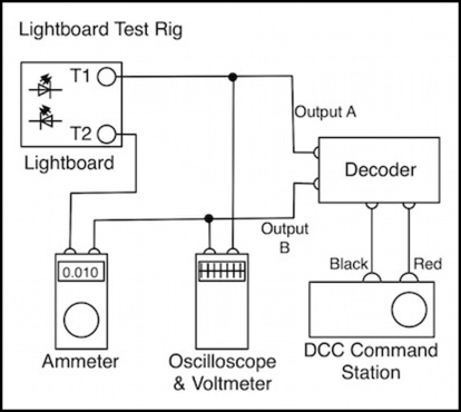
The Command Station here is my Zephyr, and it was also connected to a computer running JMRI (which makes programming decoders much easier) and my RRampMeter (simply to confirm that track voltage was correct, and it was). The Ammeter was just to check that the current was as expected (around ~18mA per the online calculator I used). The oscilloscope let me see what voltage was being output to the lightboard, and how dimming was performed (PWM or some other method).
In practice, the ammeter didn’t work very well. I’m not sure if it was confused by the PWM waveform or what, but while it worked connected to a a true DC output from a Kato power pack, it didn’t work connected to the accessory output of any decoder. The oscilloscope was a bit better, although I’m not entirely sure it was fully accurate.
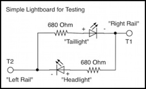
The lightboard itself was a simple set of two LEDs and two resistors on a solderless breadboard:
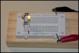
Red is “right rail”, here the taillight is lit (I used a yellow LED as I didn’t have a red one handy)
I used 680 ohms (in 1/4W size) to match the MicroAce E231 EMU’s lightboard (anything from 470 Ohms to 1 kOhm might be found in the real world). With this design, if the “right rail” input is positive, the headlight will light, the same as it would on a DC layout. Note that ordinary DCC decoder outputs are usually negative when “on”, but a bipolar output is simply two opposite polarity wires, and it doesn’t really matter which is “positive in forward”, as long as I connect that one to the “right rail” terminal of the lightboard.
There’s one more thing I needed: a dummy load for the decoders so that I could read them back. The NMRA DCC standards (RP-9.2.3) note that acknowledgement by a decoder requires switching a 60 mA load in and out of the circuit. This probably dates from a time when train lights used bulbs, that had at least a 60 mA rating. And a 60 mA change in load is also big and easy to separate our from routine variations in load from an operating decoder (it’s about 1/4 the maximum load allowed on a normal service track).
But the lightboards I’m working with draw less than 20 mA, sometimes much less. This means I can’t read those decoders on the service track (decoder manufacturers could include a resistor on the board to use instead of the attached lights, but the power dissipation requirements are quite high, 840 mW on my Zephyr and up to 1,440 mW on a maximum-voltage track, which makes it hard to do). My solution was a simple circuit with 250 Ohms of resistance (and nothing else), which creates a load a bit under 60 mA, but “close enough”. I chose this value because I had a bunch of 1 kOhm resistors handy, and four in parallel gave me 250 Ohms and plenty of power dissipation. Ideally I would have used a 1 Watt, 215 Ohm resistor, but I didn’t happen to have one of those.
Alligator-clip leads were used, so I could quickly switch the decoder from programming clipped to the service track and dummy load, and testing on the operational track with the lights. If I just needed to change CVs without checking them, I could do that with Ops Mode programming on the operational track and with the lights connected, and I used that for a number of tests.
I spent a lot of time getting familiar with the decoders, reading manuals and testing CVs to make sure they matched what the manual claimed they defaulted to. And all testing was done after first doing a decoder-reset to factory values to ensure I was starting clean.
The Decoders
I’d previously summarized my list of candidate motor car decoders, and there’s a list of ones I was considering for cab decoders on my Wired Decoders page. But here is the “short list” I actually tested. All prices are typical online “street” prices, not manufacturers recommended list prices. To get on this list, a decoder needed to have a bipolar output, and be reasonably easy to find in the U.S.; I stretched the latter point a bit for the Lenz, since it was very feature-rich for a decoder of its price, and I’d be willing to accept some inconvenience for the extra value.
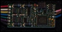
Lenz LF101XF
I’d really wanted to use the reasonably-priced (US$22) Lenz. It’s not really small (21.6mm x 12.0mm x 3.0 mm) but it has the features I want at a good price, and Lenz’s reputation behind it. I even picked up several. Unfortunately it’s been discontinued. I’d like to use the ones I have, so I tested it, but it’s not the long-term solution.
Lenz LF101XF
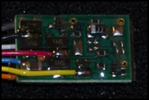
TCS M1 (or Z2)
The TCS decoder is the leading candidate among shipping decoders (because, well, it’s the only one shipping at present). It’s bipolar, and has a lot of features. The US$30 M1 is a bit larger (14.4mm x 9.1mm x 3.4mm) than the US$32 Z2 (12.95mm x 6.9mm x 2.79mm), but otherwise identical for my purposes.
TCS M1
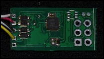
Aegaeon:C
I had a beta version of Railstars’ (Don’s) new bipolar decoder in to test as well. The US$25 (MSRP, but that’s likely to be “street” at release) decoder is quite small (11mm x 6.7mm). I should note that it is beta, and Don’s already said the final shipping one will differ. But the changes should all be improvements.
Aegaeon:C
It’s a pretty short, short list. Given how little these decoders do, that should make testing them easy, right?
Well, sort of. First I had to fight my way through the documentation. While TCS’s documentation isn’t anywhere near as horrendously bad as Digitrax’s, it’s not exactly crystal clear just what CVs exist on which models of decoders, and I had to do a bit of reading-between-the-lines to figure out how to configure the output for bipolar operation. Don’s draft documentation, while still lacking a couple of sections, was pretty clear (and I could always bug him with questions). Lenz’s, once I’d found the lf101.pdf manual through Google as it doesn’t appear in the index on Lenz’s site (although the older LF100XF does), was blissfully simple and clear. Well, almost, at a couple of points they tell me to enter “10” when they apparently mean “0”. At least Lenz has the excuse of being translated from German. You’d think native-speakers would do a better job of English than a translated German manual. But you’d be wrong, at least in TCS’s case.
Test Results
And now for the results. With Lenz out of the game, and a $5 advantage over TCS, not to mention an inconspicuous size, this is Don’s race to lose, so lets start with his Aegaeon:C.
Aegaeon:C
It works. The big lack here was that “Rule 17” lighting couldn’t be triggered by a function key, but only automatically when the train stopped (or one of the other automatic effect triggers). Don tells me he’s adding a function key for this to the final version though. Since this is primarily for bipolar applications, out of the box it’s configured for direction-sensitive bipolar operation, which makes setup trivial if you don’t want to tweak anything.
I should note that there were a number of issues due to this being the first beta (really an “alpha”) version. I didn’t encounter any hardware problems, but I found a number of software ones, most of which Don already knew about (I found some new ones too).
To make it work, the white wire connects to the “right rail” contact on the lightboard, and the yellow wire to the “left rail” contact. (well, mine was wired backwards, but that was a known problem of the beta, to be fixed in the final version).
F0 is the default on/off for the headlights (it can be remapped to another). The Rule 17 output is going to be O5, which means it can be mapped to function keys from F0 to F8 thanks to the NMRA’s rather odd standard mappings. But that’s a reasonable range for me. I’ll probably use F3, which just happens to be the default. I’m avoiding F2 since on my Zephyr this is a momentary function best used for a horn if I ever add sound, and F1 tends to be a default for other things so I’ll probably avoid it as well. F3 is the last one on the top row of function buttons, so it’s a desirable one for a frequently-used command.
A big plus on this decoder is that “full intensity” light output can be adjusted via a CV, not just the rule 17 “dim” intensity. It’s a simple linear scale, with 128 equating to about half track voltage (a reasonable “bright” light for a white LED). The “dim” setting is similarly configurable.
Consisting worked, except for the function map which was another “fixed in the final version” feature. This is important, as in a 10+5 set, I’d want the exposed end to follow the consist address, but the two cabs facing each other to follow the loco address so they can be turned off. On the other hand, given how few double-motor 10+5 sets I have, it’s not a make-or-break issue.
The decoder lock function worked, although it has some odd behavior. It’s not entirely clear if this was my decoder being wonky or something else (like me getting confused) as Don saw different behavior when he tested later. On mine, I could lock by setting one of the two CVs, but not by setting the other (but not in the way the manual suggested).
My test decoders have gone back to be re-flashed with the new firmware, and I’ll do more testing once I get them back to confirm the consisting, lock and Rule 17 stuff works as planned. But I’m not anticipating problems.
The size is a big plus. This is the smallest decoder, and is going to be easier to tuck out of sight inside a visible passenger compartment on an EMU.
So, there we go. Assuming he manages to get these to market, I’m buying (I actually have had a pre-order in since May for enough to do several trains, but as previously noted I have a lot of trains in need of decoders so like the small set of Lenz decoders I have, that’s just a start).
Lenz LF101XF
The Lenz supports Rule 17 lighting (assignable for functions F1 to F8), but not a “normally reduced” headlight setting if you are also doing Rule 17 dimming. Out of the box, it’s configured for direction-sensitive bipolar operation with F0 as the on/off function. No muss, no fuss.
To make it work, the white wire connects to the “right rail” contact on the lightboard, and the yellow wire to the “left rail” contact. Note that the decoder has a blue “common” wire, but in bipolar mode this isn’t used for the head/tail lights.
Like the Aegaeon, the “dim” setting is a 0-255 percentage scale (with 128 equal to about half track voltage). The normal brightness of the headlight can be controlled via CV50, and the taillight via CV51. A “Rule 17” dim function key can be configured via CV54 for the headlight (I set it to 4 for F3). However this also uses CV50 for the “dim” intensity, so full brightness is the full 100% level in this case; you can’t get both Rule 17 and normal intensity control.
Still, this decoder works for basic bipolar operation correctly out of the box, and a Rule 17 function was trivial to set up (set CV50 to an intensity such as 128 or 64, and set CV 54 to a function ordinal). The size is a bit of a negative: It will fit in an N-scale EMU, but just barely and it’s going to be quite obvious, either standing on edge or being placed above passenger seats.
I have several of these, and I’ll use them. And I’d rank them a close second to what the Aegaeon:C is planned to be in its final version. The big flaw, of course, is that I can’t get any more. The LF101XF is itself a successor to the earlier LF100XF, so perhaps they’ll come out with a third-generation successor eventually.
TCS M1
The TCS is not set for bipolar operation by default, rather it’s a normal motor decoder with standard function outputs. It supports a Rule 17 lighting effect (assignable to functions F0 to F6), but not a “normally dim” headlight setting (or at least I can’t find one). The manual’s description of bipolar headlight control is pretty opaque though, and it’s quite possible that I’m missing important features. It’s one of the few places their documentation really falls down. I also couldn’t get “Rule 17” lighting to work with the bipolar output. The description was quite clear for how to associate this to a function output, it just didn’t do anything when configured that way for the bipolar output.
The bipolar output uses the motor wires; so you couldn’t, for example, use this decoder for both a motor and a bipolar lightboard. It is configured by connecting the orange wire to the “right rail” contact on the lightboard, and the gray wire to the “left rail”, and then setting CV61 to be 68 plus whatever other values you want in it. By default it contains 1 to turn on BEMF, which is irrelevant in my use, but I left it there and set the CV to 69. This worked correctly, with either the headlight or the taillight coming on depending on direction, and not varying in intensity with speed. F0 controlled these lights, and turning it off kept them off regardless of direction.
Rule 17 lighting is controlled by setting CV49=8 (Rule 17 effect enabled in forward direction for F0), CV123 to the selector of the function key you want to use (I used 16 for F3), and CV64 to the “dim” intensity on a 1-6 scale (I used several, without effect). Nothing I did would make this work.
It does separately have a “headlight intensity” setting in CV157 (same 1-6 scale), and this did work to reduce the normal brightness of the headlight.
TCS has a “dim on stop” function, which I didn’t test as that’s not the kind of Rule 17 function I want (and I didn’t really expect it to work given the lack of support for the other mode).
Given that the Z2 is essentially identical I didn’t bother to test it. I also didn’t test consisting because: a) I expect it to work, and b) I was sufficiently disappointed by the lack of working Rule 17 lighting to lose interest in the decoder.
The M1 works and meets my minimum requirement, but the lack of Rule 17 is a disappointment. I may go back and do some more testing of these later, but for now I don’t believe it works, and I’m disappointed by that.
Conclusion
Well, as I said at the start, any decoder that did basic bipolar cheaply would probably be my selection. I was in luck, and the best decoder for my needs (assuming all the beta glitches get fixed) is also the cheapest (well, the cheapest still on the market). That’s a win.
Any of the three would have worked though. While the Lenz was really the cheapest, given the size difference I’d still have gone with the Aegaeon if I’d had a choice. And the TCS at $30 was more money for less functionality. If it were the only option TCS would be acceptable. With the others available, it holds a clear third place.
Outage Notice
My ISP has notified me that they’re doing server maintenance on Saturday, February 9th. There may be periods when the server supporting the commenting system is down because of this, although that’s expected to be of limited duration.