


DCC Speed Tables
Update 11/25: as Don points out in the comments, I got a couple of things wrong about Speed Tables and BEMF. I’m going to leave this post unchanged (except for a couple of correction comments), but the separate pages on those topics have been corrected.
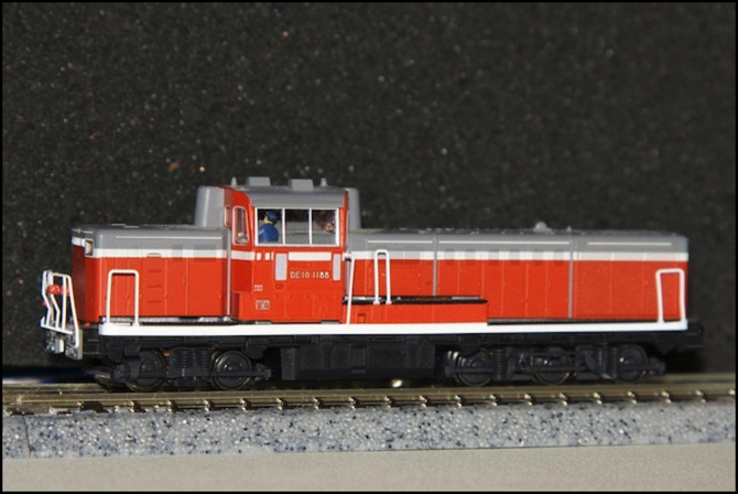
My plans to start installing decoders were somewhat upset when a large quantity of the ones I’d ordered turned out to be out-of-stock, and a box arrived containing only a couple of decoders and some wire. I actually have a number of decoders on hand, though not enough to do a full EMU the way I want, or all of the models I wanted to experiment with. So, while I could have made a start, instead I decided to spend some time working out my standard configuration settings for the Digitrax decoders. I’m going to have a number of these even if I don’t use the DZ125 wire-in decoders, since my Kato “DCC Friendly” models use Kato’s EM13, which is essentially a Digitrax FX3-Series decoder. And I have a few models, like the DE10 above, with lightboard replacement Digitrax decoders.
Note: I’ve collected a bunch of information related to the decoders I’m considering using over time, and put it on my DCC Decoders page, along with a couple of subordinate pages that address specific topics of interest to me. That’s been augmented by some new research in recent weeks as I get closer to defining how I want to configure my decoders. I’ve included much basic information about speed tables and related adjustments on my Speed Tables page, although a lot of it is repeated below.
In the case of my DE10, it’s equipped with a DN163K1D, the installation of which was described previously. Although I’ve been using this for quite some time for various tests, I’d never programmed the decoder at all (except for enabling transponding during some testing) and had reset it to factory defaults several times over the course of the testing. It was still set to address 3.
First, since I’m programming this with JMRI, I put it on the programming track and loaded a bunch of the pre-programmed CVs from the decoder into the software, since the defaults set in the software aren’t quite identical to those in the decoder. Then I saved those so I’d have an accurate reference on the screen as I made changes. That done, I assigned the next free address, which since this was the first assignment I’d made for a locomotive (or anything) was 1010 per my addressing scheme.
After confirming that the loco still worked by running it around the test track, I painted the address on the underside of the fuel tank, along with an “F” to mark the front end of the loco for reference. It’s official: my first “programmed” DCC decoder for Sumida Crossing. Now to finish programming it...
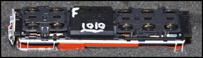
I’d planned to use some markers, but none of the ones I tried showed up against a black background. So I just used some of my usual model paint, and a fine-tipped brush.
While I was at it, I also added an EM13 and two FL12’s to my Chūō E233, and gave it the first EMU address (2010).
Speed Tables
With that, I decided to work on the speed tables first. My command stations use 128 steps, and my decoders are all set to 28/128 speed step operation, so I’ll be using the “advanced” table in the Digitrax decoders, CVs 66 through 95. This is an implementation of the table described in the NMRA’s RP 9.2.2., and consists of 28 individual steps, plus two “trim” CVs (66 and 95) used as multipliers for forward and reverse, and another (CV65) used to “kick start” a stationary train. The multipliers default to 128 (0x80), which is 100% per the Digitrax documentation, so I don’t need to change those. The table itself is scaled from 3% to 98% in even steps of about 3.5% by default (values 8 to 251).
Note: the NMRA didn’t say what the values in the speed table’s various CVs mean specifically (correction: oh yes they did), so what works for Digitrax won’t necessarily work for anyone else. Some adjustment is likely. However, that’s always going to be the case for any new decoder, as the behavior of the model depends on the specifics of the motor and drive train, which is likely to vary even between “identical” models.
My goal with speed tables is to have the throttle setting on my DT400 throttles relate to the scale speed of the train in some predictable manner. I may use two different scales: one for narrow-gauge trains limited to 130 kph, and another for the Shinkansen and high-speed narrow-gauge trains. To do that, I’ll have to allow for the fact that the throttle setting displayed is a 0-99 scale, but the throttle value (“speed step” to be formal) sent to the decoder is a 0-127 scale, and the two are roughly linearly related by default (so 99 equals 127, and 50 equals 65, which I learned using JMRI to monitor commands sent on the LocoNet as I adjusted the throttle).
For EMUs, I’ll either have 99 mean top speed for that model of locomotive (e.g., 95 kph for the DE10), or I’ll have it mean 130 kph as the top speed of the class. The latter has the benefit that all of the EMUs (except for a couple of high-speed models, and the Shinkansen) would use the same scale. I haven’t yet decided if I want a linear scale (e.g., if 99 = 130 kph, then 50 = 65 kph) or if I want to have a wider scale at the low end (e.g., use 0-80 on the throttle to mean 0-50 kph or so, so I have finer grain control at lower speeds). More thought is needed on that before I get to final programming although I’ve summarized my current rough plan below.
Calibration
I also need to figure out how a throttle setting sent to the decoder gets mapped by the speed table into a locomotive speed. This is going to vary for each train, or at least each class of train, due to motor and gearing differences. But once I work out a system for calibrating the scale, it should be fairly easy to adjust from one loco or EMU motor-car to the next. So, what do I need to set the speed table to, for “99” on the throttle, or “127” on LocoNet, to equate to a specific top speed like 95 kph?
I started with the DE10, and set it on the Bachrus speedometer cradle to see what 100% equated to, before enabling the table. Unfortunately, the DE10 is just too light for the speedometer to work reliably at high speeds, and the wheel kept losing contact, causing erratic and too-low readings. I eventually gave up, and put the loco on my test track loop.
On the test track, which is 2,268mm long, I ran the loco at top speed and timed one loop with a stopwatch, calculating scale meters/second, and then converting that to scale kph. Run at maximum throttle on my Zephyr (which equated to a throttle setting of 126 being sent to the decoder; apparently my Zephyr won’t send 127). This came out to around 250 scale kph, just slightly fast for a locomotive with a prototypical top speed of 95 kph!
I set the speed table to a value that I thought would proportionally get me close to 95 kph. When you lower the top slider, it lowers all of the ones below it to be no higher, so I ended up with half the throttle’s range set identically, which made testing easy. Unfortunately it was still way too fast (loco speed doesn’t appear to be linear with the decoder settings). Much experimentation later, and I discovered that a setting of 61 (out of 255) gave me a speed of 93.9 kph, while 65 gave me 98.5 kph, so the ideal setting would be close to 63, except that JMRI’s slider wouldn’t let me set that value.
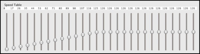
JMRI Panel with Speed Table Setting used to test maximum speed (capped at 126/255 in this example)
Track Voltage
While I was doing that, it struck me that what the decoder is doing is letting through a percentage of track voltage (yes, that would have been obvious if I thought of it, but I had my mind on other aspects). Now that’s nominally 12 volts, but it’s going to vary, perhaps by as much as 20% due to loss in wiring and track joiners, so I’m never going to be very precise here. I’d like to aim to be within a few scale kph in my configurations, so trains on adjacent tracks set to the same “speed” will actually be going close to the same speed. But even if all my trains are set to 100 kph +/- 2 kph, in reality they could be going anywhere from 80 to 100 kph by the time I allow for variable loss in the track voltage.
And while thinking about that, it struck me that my bench system is a Zephyr that puts out ~13.9 V DCC, while my layout uses a more precisely adjusted DCS100, that’s putting out a real 12.0 V DCC (both of those drop under load). That could introduce a 15% speed reduction from bench to layout, even before allowing for track loss.
So I took my train, going its scale 93.9 kph at what turned out to be 13.7 V DCC, and ran it around the layout, averaging 59.3 scale kph in one loop at full throttle. That was a 37% reduction, which was rather dishearteningly large. I suspect the problem is a combination of more variation in track voltage on the layout than on the short, and very clean, test track, plus non-linearity in the motor itself. In short, 24% of something 1-2 volts less than 12 volts, is probably turning the motor significantly slower under load than 24% of ~13.7 volts. It could actually be linear, if my track voltage is around 10 volts, but I didn’t think it was that bad. Later testing convinced me that motor behavior follows the speed table settings fairly linearly, so I’m less certain why there’s such a large change going from 13.7V to ~11V.
Similarly, I ran my Chūō E233, and found that on the Zephyr the default top speed was a scale 249 kph. With speed table enabled, and top speed limited to 102/255, the top speed on the Zephyr test track was a scale 158 kph. On the layout it was a scale 104 kph, although there were a couple of spots where it slowed down (the DE10 didn’t have this problem, so I’m unsure of the cause, but the E233 seems to have less reliable electrical pick-up).
What this means is that I’m going to have to use the actual layout to calibrate my decoder’s speed settings. That’s a nuisance, not least because it takes a very long time for a train to make a loop at prototypical speeds: the outer loop of the layout is 8,527mm long, which in 1:150 scale is 1.28 scale km of track, or for a Shinkansen in 1:160 scale that would be 1.36 km. A commuter train going 110 scale kph takes about 42 seconds for a full loop. It also suggests that I’m better off with a linear scale, since I’ll need to calibrate fewer speed settings per train (maybe 1/4, 1/2, 3/4 and full).
Before I make a final decision there are two more things I need to check out: how properly-calibrated BEMF affects this, if at all, and how much variation there is between the DE10 and one of my EM13-equipped EMUs.
Load and BEMF
One problem with the speedometer-based testing, and one advantage of test-track testing, is that speed could vary depending on the load, and the load depends on the other cars in the train. A “light” engine with no cars will move faster than one pulling a twenty-car freight, and similarly an EMU with ten cars is going to behave differently from the motor car alone. To really get throttle to equate to speed, I probably need to test using a “typical” size train. Or at least, that’s my theory.
(comment: some of the following description of how BEMF works is wrong, see the BEMF page for a corrected description)
Back-EMF is a decoder feature that adjusts the voltage sent to the motor as the demand varies with a constant throttle setting, to try to maintain the motor at a constant speed. It’s basically sensing an indicator of the motor load (the current drawn by the motor) and using that to provide more voltage when the motor is under heavier load, as it is when starting or climbing a grade). Enabling BEMF will interact with load, so I’m going to need to work on the BEMF testing using a similarly “typical” train to start, although if it works as promised a light engine and a loaded one should run at the same speed for a given throttle setting (on the same track voltage).
In most decoders, the BEMF control algorithm needs to be calibrated to the specific model of train, which is something of a trial-and-error procedure. I’ve written it up on a BEMF page, so I won’t repeat the details here. I’m going to start with the speed table set to be a linear table from zero to a scale 120 kph (measured on the layout). Then I’ll adjust BEMF as per the directions, and see if taking away the rest of the train has any effect on speed. I’m rather hoping it doesn’t, as that will allow me to re-calibrate BEMF and the speed-tables independently of each other.
And that’s likely to be important for some trains, as BEMF for trains run in a consist can require a different set of settings from BEMF for trains run independently (because the two motors fight against each other and can confuse each other’s control algorithms). And a couple of my 10+5 sets will run in a consist since they have two motor cars in the train.
Note: the TCS M1 decoder’s BEMF is self-calibrating, which would be nice, except that given what I know about the complexities of the algorithm involved, I don’t think it can be effectively self-calibrating for all trains. And with no way to override the self-calibration, I’d be left with the choice of turning it off if it misbehaves. Some of my planned decoder testing is to see if I do have any problems with the M1.
Calibration II
So, I need to test under load, on the layout, and with BEMF enabled and tuned. So first, the train goes on the test track and gets BEMF tuned both alone and with a prototypical string of cars. This immediately ran into a hitch: configuring BEMF is, per Digitrax, a trial-end-error process where you enable it (via CV57, although by default it’s already enabled) and then adjust first CV57 up from 128 until “surging” occurs, then adjust CV56 up from 48 until “oscillation” occurs. I got both of them to 255 without seeing any problems. I’m fairly sure it was configured properly, and it may just be that the DE10 is too light, free-running, and responsive to have any problems with the servo loop.
I need to configure it with a load, but the DE10 presently lacks couplers, so I set up the Chūō E233 and ran it to see how a ten-car EMU reacts. Oddly, it ran just the same as the DE10 in the sense that I couldn’t get BEMF to misbehave, and wound up with both CVs set to 255. On the other hand, running it on the track it clearly slowed on hills, so CV55=6 is too low. But Digitrax says to adjust that one last. That’s where I am at present: preparing to experiment with BEMF settings. I have a provisional speed table that lets the E233 run at realistic speeds, although it’s not a final speed table by any means.
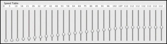
E233 Speed Table for Testing BEMF (112/255 equates to ~120 scale kph on my 12V layout)
Interesting Speeds
So what speeds matter in a speed table? That’s going to depend on the trains being run, and the rules of operation that apply to them (e.g., what does “slow” or “restricted” speed mean for a given type of train). Here’s a list of some typical values for Japanese trains:
Shinkansen-only:
- 320 kph: Newer Shinkansen top speed (my E5, among others)
- 300 kph: Top speed of the 500 Series, often limited to less
- 275 kph: Top speed of many Shinkansen
- 240 kph: Top speed of older Shinkansen, such as the E4
There are a couple of other speeds (e.g., 260, 265) I’m omitting from this list since they’re so close to other speeds.
All Trains:
- 160 kph: Top speed of some narrow-gauge trains
- 130 kph: Top speed of Mini-Shinkansen on converted lines, and many other trains
- 120 kph: Top speed on many commuter lines
- 110 kph: Top speed for “Class A” express freight and many commuter trains
- 95 kph: Top speed for “Class B” express freight
- 75 kph: Top speed for “Class A” dedicated freight, and “Reduced Speed” per signal
- 50 kph: Approximate meaning of “Caution” indication on signals
- 25 kph: Approximate meaning of “Restricted” indication on signals
Signals can mean different speeds on different lines or railroads, so the above is rounded somewhat.
The other factor is that Shinkansen are 1:160 scale, but all of my other trains are 1:150 scale. So do I use the lower settings for 1:150 scale speeds for all trains, so a Shinkansen will run at the same “restricted” speed as a commuter train, from the perspective of the observer? Or do I ignore the problem since the variation is within my error range at low speeds, and just set the Shinkansen using 1:160 so the top speed is correct for the scale of the model?
And I have a dozen speeds, but many of my trains will only need to run at the lowest four or five of these. I’m tempted to divide my 0-99 scale up using a simple (and somewhat approximate) “divide by two” approach for the bottom 8 values (with individual trains limited to their maximum). This would mean my DE10 would hit 95 kph at “47” and not go any faster at higher settings, giving up half the range. But my M250 would hit 130 at “65” before reaching it’s limit, and a throttle of “80” would mean 160 kph (but would mainly be used by Shinkansen). All trains would then react to a “caution” signal with a throttle setting of “25” (50 scale kph). Above the “80” (160 scale kph) setting, the scale could be linear up to the maximum for the train (so “99” would make the E5 go 320 scale kph, and the 500 Series go 300 scale kph, but it would still make the DE10 go just 95 kph).
One variant of that would be to make “90” equate to 275 kph (since it’s so common as a line maximum), with a linear scale below it and a different linear scale above it to the train’s maximum.
I need to think on that some more before I program the final speed tables, but that’s how my thoughts are shaping at present.