


Decoder Programming Prep
As noted last time, I’m going to (finally) install DCC decoders in some of my commuter (and other) trains that aren’t Kato “DCC Friendly” designs, meaning I have to use wire-in decoders. And since these are EMUs where the motor car is in the middle of the train, that means installing three decoders per train, a Motor Decoder and two “function-only” decoders for the cab cars.
But to start with, I need to set up my workspace since it’s been a while since the last decoder install, and the various elements had all moved off the bench to other uses. And the bench had filled up with important stuff (meaning junk I couldn’t stuff somewhere else), so I needed a better workspace. Besides, I’m going to want to sit down for this work, and the workbench is really better for standing work.
So the first order of business was to clear a space off the dinning-room table I use for a variety of things that don’t involve food (it’s home to my computer’s printer and a fax machine among other things), and set up on it. I want to protect the table since it’s a good one, so I put down a couple of large sheets of 1/2” foamcore topped with a large sheet of cardboard. This way any dropped tools, heat from computers or other things, or drips of solder won’t damage the tabletop.
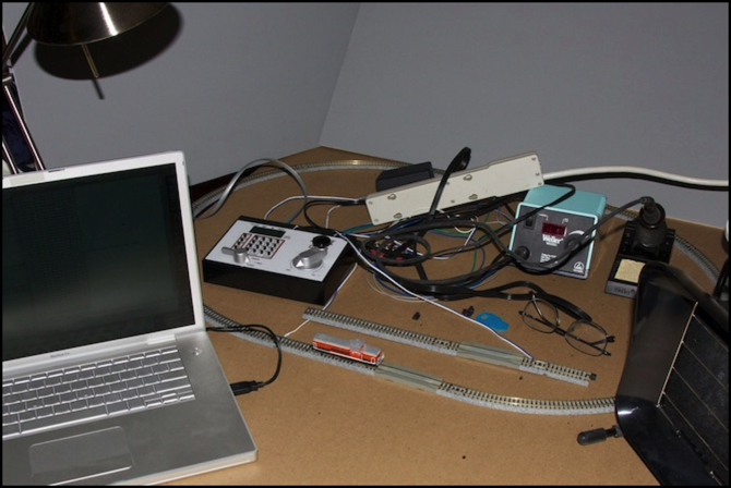
Atop this, I set up:
- A very bright halogen desk lamp
- A loop of test track and a short length of programming track, both connected to,
- The Digitrax Zephyr I use for “bench” work
- The RR-CirKits LocoNet USB interface
- The laptop running JMRI software for programming decoders
- My Weller WESD51 soldering station and exhaust fan
- My decoder-tester (an ESU 51900)
and a variety of tools, pads of paper, the iPad I use for decoder manuals and other things.
I didn’t bother to rig up a DC power pack and A/B switch for the test track, since I could do my DC testing on the layout. If I ever get to having the luxury of a permanent test/programming bench, I’ll do that. I did however include a Kato power pack connected to a short segment of track, for testing cab lights and other things where I need DC with a polarity switch.
While I was at it, I upgraded the JMRI software since it was a year old, and after cleaning the test track, I ran my DCC-equipped DE10 around to make sure the track was wired up properly, and the software could see the status messages from the Zephyr. This is a Kato model with a Digitrax DN163K1D decoder that I’ve used for other tests, and it will likely be the first decoder I fully program.
My tools for this work will include:
- Anti-static wrist strap
- small-gauge wire cutters
- needle-nose pliers
- soldering “third hand” clamps and a collection of heat sinks
And my camera on a tripod to document the work.
Speedometer
Finally I had one more thing to install. Since I’m planning to program speed tables, I need to know how fast the car is running, and I don’t want to sit there timing the train around the test track with a stop watch. I bought a speedometer for just this purpose a while back, and it’s finally time to install it and see how it works.
What I bought was a Bachrus MTS-DCC (40 Series, for N scale), which consists of a small unit that sits on the track with a pair of rollers atop it, and a device to convert its output to USB. There’s no separate software, as support is built into JMRI. However, you do need a “cradle”, a set of additional rollers to hold up the rest of the train. I bought the 40SA-3 set, which has three rollers, so with the speedometer a total of four. They sell other size sets, or you can use somebody else’s (although height could be an issue).
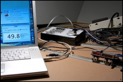
JMRI Speedometer and Bachrus MTS-DCC holding DE10 locomotive
The software aspect puzzled me for a while, as the manual and online video examples are only for Windows, and the CDROM only contained a standard (and outdated) copy of JMRI in the Mac folder (I have a Mac), but my new copy of JMRI wouldn’t read the speedometer. I finally figured out that there wasn’t any driver install needed on OSX, but that it needed to be set to use the /dev/tty.usbmodem1d11 driver in the JMRI DecoderPro Preferences pull-down, not the /dev/tty.usbserial-FTNOEWXS driver (which is used by my LocoNet interface). That solved, the speedometer and the LocoNet interface happily coexisted, and I could use both at the same time.
Note: shortly after that, I added a USB hub and plugged the Bachrus into that (I ran out of USB ports) and the tty device name changed, which confused JMRI until I figured out what had happened and selected the new one.
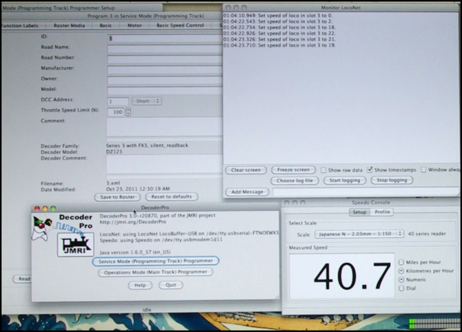
DecoderPro showing the LocoNet monitor (top right, reading the throttle setting) and the speedometer (lower right)
JMRI even has a setting for “Japanese N 1:150” scale on the speedometer (as well as both kph and mph scales). In the photo above, you can see (barely) that my DE10 is running at 40.7 kph with the throttle set to 19. This is with an out-of-the-box config, not yet speed-table adjusted.
The Bachrus works, but getting the model into it to be tested is a real pain. The sensor just balances on the track, and it’s got a big bulge and a stiff cord on one side, which tend to make it tip. An N-scale loco isn’t heavy enough to hold it in place. I eventually resorted to wedging some spare track under it, and taping the whole thing down to the cardboard tabletop using masking tape. Inelegant, but effective.
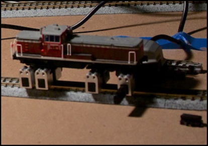
DE10 in Bachrus Cradle/Speedometer (unit at right end is sensor)
All that occupied a pair of evenings while I await the arrival of my decoders. So next I turned my attention to planning the work.
Planning the First Conversion
My first victim, I mean subject, is my MicroAce Sobu E231. I actually have two of these; one has some running problems as the result of a mishap when breaking it in (I need to tear it down, clean and lube it, but that’s another project). I figure with two, and one running poorly, I can always steal parts from the bad one if I screw up too seriously. That’s not too likely, but I’m not going to risk one of my more favorite trains as the first conversion.
The first order of business was to put the motor and cab cars on the layout, and run them on DC so I’d know how they sound and confirm that they were still working, since it’s been more than a year since the train was last run. Then it was off to the bench, to tear them down and see what I had to work with.
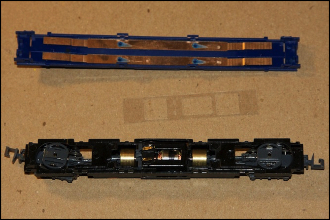
Sobu E231 Motor Car
The body lifts off the motor car quite easily. Separating the blue interior from the black undercarriage is a bit more work, involving four clips along each side. Open them on one side, carefully, and the parts come apart (I used a small jeweler’s screwdriver and much care). This reveals the motor with two brass tabs sticking up, and the brass strips that run along inside the blue part, on which the truck pickup contacts and the motor tabs rub. Both trucks are connected to both rails, and that’s something I want to preserve, so cutting the brass strip is undesirable.
Ideally I’ll insulate the strip above the motor, drill a small hole in the blue plastic between the strips, feed the decoders “motor” wires down and connect to the motor tabs, and connect the decoders “rail” wires to the strips somewhere else (possibly through the same hole). Clearances are very tight, and I could end up removing some of the blue plastic, but I’d like to avoid that.
The cab car body was harder to separate, but with persistence it came off (it’s the same basic approach as a Kato EMU: pry the sides away from the frame at the end away from the cab until you can lift that end of the body up a ways, then the rest slides out easily). The blue interior isn’t as easy to separate (I still haven’t figured out how it clips to the underframe); I’ll get a more complete take-apart page written once I’ve figured it out.
Meanwhile, the cab eventually unsnapped from the interior, revealing the lightboard (I’m still not sure just what I did to release it). Before I took it off, I put the bodyless cab on a bit of DC track to check out the operation of the lights. There are three of these: an always-on LED that illuminates the light-pipe to the destination sign, and two head/tail lights that shine through the front of the cab.
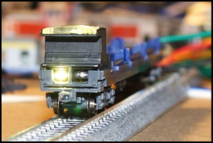
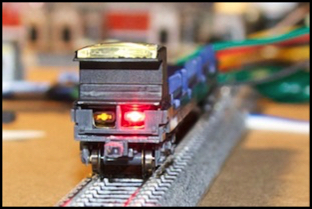
Headlight (left) and taillight (right) - in both the top destination bar is lit, but hard to see
Note: when one LED is lit, the other is off; it looks like it’s on in these photos, but that’s a reflection from the flash.
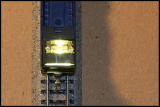
Top-down view of the third light
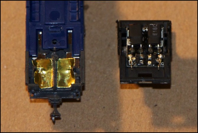
All of these are on a lightboard (above right) that has two whiskers that rest on the brass strips under the cab. With a bipolar decoder, I think I just need to insulate the brass, and wire to the whiskers. However, the way the brass curves up, it’s possible it’s making contact in more than one place. I need to to some checking with powered wires to make sure the lightboard works with just the two whiskers powered.
The lightboard is a bit complicated. The two black things in the photo above are the head/tail light fixtures, mounted on the underside of the board, along with the pickups and three very small black rectangles of unclear purpose. There may also be something underneath the black things; I need to take a closer look at that part of the board.
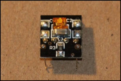
Lightboard, top
The top of the lightboard holds the third light (orange block), a resistor (marked R3, which suggests the black rectangles on the other side might be resistors, but if so very small even for SMD resistors. And just below the light is something marked C3 that looks like a surface-mount capacitor (and see the C1/C2 markings at the top of the board, suggesting there are capacitors on the other side of the board under the light fixtures). I don’t think I want to try attaching separate function outputs to this board, so going for a bipolar-output cab decoder is probably the right answer.