


Revisiting Arduino
Two years ago I wrote about my plans to use an Arduino to control a pair of trams on a double-track line sharing single-track stations at each end, replicating the design of the Tōkyū Setagaya line. That’s briefly written up in that earlier post, and I also have a full page about the project that goes into more detail, with a sub-page about the current testing work.
Back then I bought an Arduino Mega 2560 and a bunch of other parts including a “shield” used to drive DC motors, loaded the basic test program that blinks a LED into it just to convince myself I could do it and the hardware worked, and then put it on a shelf for “later”. And forgot all about it while I worked on other things, only infrequently looking at the empty tram tracks and thinking “I really should figure out how to make that work.” It’s not like I dislike the work: I enjoy both programming and soldering simple circuits together. I just never could work myself up to starting what I expected to be a fairly major project. It was always: “I’ll work on that after I finish project ‘X’”, but there was always another “X” to occupy me.
This week, I finally pulled the Arduino off its shelf and started the long-ignored work.
If you don’t know what an Arduino is, it’s a small computer that can run one program at a time, stored on internal memory (no disks or keyboards, at least not in a simple application of one), designed to receive and transmit electrical signals on pins to control things. They’re aimed at the hobbyist market, and allow people to do all sorts of interesting things with a fairly minimal level of electrical and programming skills. Minimal isn’t “none” however, particularly if you’re trying to do something reasonably complicated. And of course I am. You can even buy them at Radio Shack now, which turned out to be handy.
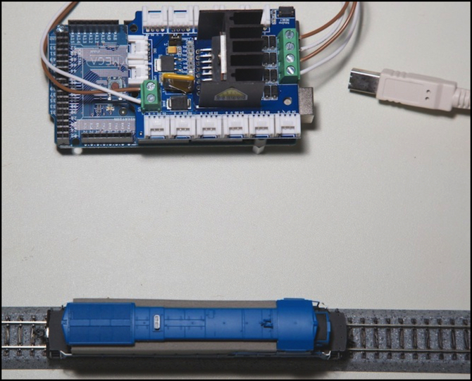
The cool thing about the Arduino (well, one of many) is that it’s very well designed to control small DC motors, and there are kits to make that even easier. In the photo below, the blue board is the Arduino itself, and the red board is an Ardumoto board (which for obscure reasons the Arduino folks call a “shield”) that allows it to control up to two small DC motors. In theory, the board can handle up to two amps, although without special heat-sinking it’s limited to about 600 mA. But that should be enough to run two trams.
In order to use this as a controller, there are three things I need to do with it:
1) Provide two PWM-based throttles for the two motor outputs (A & B) on the Ardumoto.
2) Read photoelectric sensors that will tell me where on the track my trams are.
3) Control a set of relays that will determine which track blocks are connected to which throttles at any given instant.
And to do that, I need to write the program that will be loaded into the Arduino. This isn’t rocket science. Many people have done similar things, although I don’t know of anyone who has done all three for a two-train controller, and I can learn from their experiences.
The box of parts with the optical sensors has been sitting on a shelf for two years, and I though I’d see how hard it was to make one of those work, that being the most interesting bit of programming on this project. But first I thought I’d do a quick test of the motor controllers just to make sure I understood those.
So first, I needed to get the Arduino out and wired up, and run a train on a simple back-and-forth test. I updated the development software to the current version, wired up my Arduino on the workbench, and then the fun started. Really, hundreds if not thousands of people have done this before, how hard could it be? Yeah, you see that coming, don’t you.
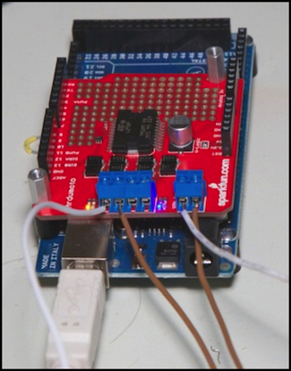
Arduino under test
Note: in the photo above, the right blue connector is an option, which is required to connect the separate power supply for the motor. To use it, you need to cut off the Vin pin on the bottom of the red Ardumoto board to isolate it from the Arduino (don’t cut the ground or other voltage pins used for logic voltages; those are required). For testing, I have the Arduino powered off the USB cable, and the Ardumoto powered off a benchtop supply with an on/off switch, so I can quickly turn it off when needed. My test track is presently wired to the “B” motor, on the left two terminals of the four-position connector.
PWM
I really didn’t want to write more words about PWM this soon, but of course it was PWM that threw me. I wrote a simple program to make one train move back and forth on a bit of straight track using timers (it took all of a dozen lines of code), updated my software (which was two years out of date), loaded the program. And the loco just sat there. And sang to me. This was supposed to be a quick test before I moved on to the fun stuff, but I began to think that wasn’t going to be the case.
Checking with my scope revealed that sure enough the Arduino was putting out PWM at 489 Hz, and my sacrificial bargain-table loco I use for testing REALLY didn’t like that. At 32/256 throttle (and at 64/256) it’s not developing enough torque to make the motor turn, so it just sits there. But ~500 Hz is enough to make the motor vibrate quite a bit, hence the “singing”. I found out later the throttle had to be much higher, above 50%, before the loco would begin to move.
I don’t want low-frequency PWM for my tram motors. Preferably I want something like “supersonic” PWM (16 kHz or higher). Aside from the nosie issue, in the event I run “coreless” motors (as the Unitram is reputed to be), it’s better to use higher PWM, like 32 kHz; low frequency PWM can damage a coreless motor by overheating it).
A quick bit of reading, and it turns out that the PWM frequency is, to a limited extent, programmable. I rather thought it would be from my work with DCC decoders, since the chip on the Arduino is really just a super-sized version of the chips used there, with a bit more functionality. Unfortunately, it also turns out that just what you need to do depends on the specific model of Arduino, and most people use the older chips, while I bought one of the quite new (at the time) Mega chips. Had I bought the Uno I’d originally planned to use (and still plan to use on the layout) it would have been much easier.
After a good bit of wasted time, I gave up and read the relevant parts of the 477 page data sheet, and took copious notes. I’d done a bit of online reading by that point, so I was beginning to understand what my problem was. I also opened up the source files for the Arduino programming environment, to look at what some of their internal commands, like analogWrite, were actually doing to set the PWM up.
Here’s the thing: on the Uno (and similar models), Timer2 is programmed to control both pin 3 (motor A) and pin 11 (motor B). Each of these has an associated comparison register (OCR2A and OCR2B) which is where you stick the 0-255 value for the motor speed (which is all done for you if you use the standard commands described for controlling motors).
With the Mega 2560, there are two timers. Motor A uses Timer3 with OCR3C, and Motor B uses Timer1 with OCR1A. Which all made sense, except that Timer3 uses configuration register TCCR3A, not TCCR3C as I expected (it’s associated with the timer, not the OCR). Once I got that through my thick head, all it took to make it work was some initial setup of the two PWM systems:
For “Fast PWM”:
TCCR3A = _BV(COM3C1) | _BV(WGM30);
TCCR3B = _BV(WGM32) | 1;
TCCR1A = _BV(COM1A1) | _BV(WGM10);
TCCR1B = _BV(WGM12) | 1;
Or for “Phase Correct PWM”:
TCCR3A = _BV(COM3C1) | _BV(WGM30);
TCCR3B = 1;
TCCR1A = _BV(COM1A1) | _BV(WGM10);
TCCR1B = 1;
What all this is doing is just setting individual bits in the register, using names defined in the data sheet for each bit (like “WGM30”) to say which bit is the output (that’s the “COM3C1” and similar) and the type of PWM being used. Setting WGMn0 alone selects “Phase Correct 8 Bit PWM”; if you also set WGMn2 you’d get “Fast 8-bit PWM” and twice the PWM frequency. Which registers to use (the TCCRnA and TCCRnB names) and which bits all change depending on the model of Arduino and the pins connecting it to the Shield.
Now there’s a bit more to it than that. You have to set up the pins as outputs (using the usual command), and I think you need to set the OCR register directly to control the speed (I saw some odd behavior when I tried to use the standard command, and it’s doing some other things that might interfere). But I wrapped it all up in a short program, which works. And while some online comments suggested all I needed to set was the register containing the scaling number (the “1”), when I did that it didn’t work.
Of the two choices, “Phase Correct” is more important for motors that need to be synchronized (like wheels on a robot), while for my purposes either mode is essentially identical, but with two of them I have additional frequencies of PWM available (there’s actually a more complex method the would yield even more by letting me use a 0-128 or 0-64 throttle, doubling the PWM frequency at each step, but I don’t need that option).
The two registers being set to “1” are setting the PWM frequency to its highest value, which turned out to be 31.354 kHz in the phase-correct PWM and 62.46 kHz in Fast PWM. The next possible value is a factor of 8 lower on each (the next one down is 7.807 kHz, via fast PWM), so those two are my basic choices, and as I want to be above 16 kHz, I’m going to be using at least 31 kHz PWM. One thing I discovered was that the loco would run faster at 64 kHz than at 31 kHz. For a tram application speed isn’t critical, and there will be more switching loss (more heat on the circuit board) at faster speeds, so I’ll probably end up using 31 kHz.
Note that the Arduino generates the PWM signal, so the frequency is a function of the clock speed used there. Most current Arduinos use a 16 MHz clock, so the above holds across most models and regardless of the shield used. There are some Arduinos with different clocks, most commonly 8 MHz, where use of fast PWM would be required to get the 31 kHz clock, but Phase Correct would provide a 16 kHz clock, which might be acceptable.
In the end my train test worked, and it wasn’t as hard as I thought it was going to be when I first looked at how to do PWM, merely very, very, obscure. And now I can start thinking about part 2, making the sensors work. But wait, there’s more.
A Visit to Radio Shack
In the middle of this, I made a trip to Radio Shack for parts, and to check out their Arduino section. I’d noticed they had one on my last visit, but hadn’t really looked at it. And to my surprise, not only are they stocking the Arduino Uno, but they had two different motor shields, one of their own, and one from seeed studio (yes, they spell it that way and in lower-case). There’s more about this on my testing page, but I picked up one of the seeed ones to play with. That’s it, mounted to my Arduino Mega 2560, at the top of the post, and in the left photo below.
It works well, and fits better atop the Arduino than the Ardumoto shield does. clearing the top of the USB connector by about a half millimeter, but with all pins solidly engaged:
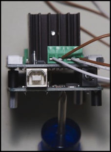
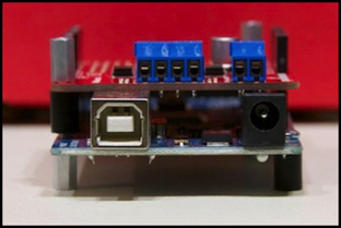
Seeed shield (left) and Ardumoto shield (right), both mounted to Arduino Mega
I had planned to also test with an Arduino Leonardo, which replaces the big USB connector with a smaller one, and shouldn’t have clearance issues with the Ardumoto. Unfortunately, it uses a new micro-USB connector, and I bought a mini-USB cable (of which I already have dozens), so that will get tested another day.
But both shields work on my Mega, and my motor-test program (no longer quite so short) works with both. I’ve put the source for that up on my site, just unzip and save it to a place where you can open it from the Arduino application. It’s defaulting to the Ardumoto shield, and you’ll need to change a constant to make it work with the seeed shield. It’s also only tested with the Mega 2560 (which should work for older Megas as well). There’s code in there to build it properly to run on older 168/328 Arduinos as well as the new Leonardo, but that’s untested. You don’t need to select that, however, it will figure it out on its own.
It should work, but bugs are ever-present. It starts with a delay of several seconds, to let you start the serial monitor, before activating the throttles. The throttle values are fixed (edit the main loop to change them). All it does is move the loco back and forth about 8” (20 cm). It will output messages to the serial monitor explaining what it is doing. If you try to run it on an Arduino it doesn’t support, it will blink the pin 13 LED in an SOS pattern.
I will warn that this is really, really, alpha code. I’ve only tested it with my sacrificial B23. If you run it with something valuable, and it bursts into flames, don’t blame me. That said, you can download it here.
Note: the program as written only compiles on the Mega. I should have tested that, even if I didn’t have a working model of anything else to load it into.
And that’s it for now. I have more work to do, but item #1 on my list seems to be crossed off: I have a working throttle that runs a train quietly at a preset speed, and that’s my main need. I might elaborate this to allow more gradual start up and slow down (right now it just goes from stop to the configured speed in one gulp). And I want to check it out with a Leonardo and an Uno (one of the latter is on order, and I need a cable for the former I won’t be able to get for several days). But perhaps soon I’ll get back to looking at the photocells.