


LocoNet Overview
This page described LocoNet in the context of my original version of the Sumida Crossing layout. It’s a bit stale. See the LocoNet page in the Layout Control section for newer information specific to that bus, or other pages in that section for other material.
In DCC systems, the “Control Bus” is a general form of communication between different DCC devices other than the communication from the Command Station (and any optional boosters) and the train itself. At present, there is no standard, and each manufacturer has their own proprietary method, or more than one, or none at all.
The “control bus” can actually be thought of as several different kinds of communication:
Throttle (hand-held unit) to Command Station, which may be wired or wireless, or both.
Command Station to Booster(s), also called the Power Station Interface
Throttle (or Command Station) and/or Computer to/from accessory devices
Of these, the last may be considered as a control bus separate from the others (also known as an Accessory Bus), or it may be merged with either or both of the others.
The NMRA’s DCC standards do not define the link between the throttle (the hand-held controller) and the command station. This means that throttles are generally sold by the same company that sells the command station, so choosing one implies the other. The NMRA did recommend a method for communications between the command station and a booster, in RP-9.1.2 Power Station Interface, but this simply transmits a clean copy of the DCC command signal to the booster for it to use. Since this is an RP, not a standard, manufacturers may do something else, and most appear to, although appearances may be deceiving.
The link between the throttle and the command station doesn’t have to use the same technology as the link between the command station and any boosters, or to accessories (many accessories just connect to the track bus and act as stationary decoders). But most manufacturers have defined a “control bus” that provides both the throttle to command station and command station to booster/accessory function, or at least one cable that carries both kinds of information on separate wires.
NMRAnet / LCC
This paragraph used to describe NMRAnet (as of 2012), which has since been replaced by LCC. It was not ready in time to be used on Sumida Crossing, although I may use it on the future layout. See my Control Bus page for more about LCC.
Digitrax LocoNet
Digitrax defined LocoNet to be a multi-vendor control bus, and there are some third-party products for it (like the RR-CirKits LocoBuffer-USB I used to connect my computer to LocoNet). This is a fairly general decentralized network based on the same fundamental technology (serial transmission of framed data segments) used by Ethernet computer networks, although it is not Ethernet, and operates at the much lower rate of 16.66Kbps, simplifying the design of devices connected to it. In Europe, Uhlenbrock is a long-time backer of LocoNet and sells some equipment compatible with it.
Additionally, because Lenz and Digitrax use an electrically-compatible method of communication between the command station and the booster (which is not LocoNet, but is on the same cable), it is possible to mix Digitrax boosters with Lenz Command Stations, or vice versa (see Digitrax’s manuals page for other supported combinations).
Sumida Crossing and Digitrax
Sumida Crossing uses a Digitrax DCC system, so my control bus is Digitrax’s LocoNet. LocoNet is also one of the reasons I chose Digitrax in the first place.
I chose Digitrax partly because I’d used it before, on my old HO network. One reason I chose it then (about ten years ago), was because of the entry-level Zephyr system (a DCS50 plus power supply), which was relatively inexpensive and easy to hook up and use. I still have that, and had initially planned to use it, but after looking at my power requirements in more detail, I decided that the 2.5 Amp output was going to be inadequate for the number of trains I was planning to run, and switched to the 5 Amp DCS100 Command Station. The DB150 is also a 5-Amp Command Station (or it can operate as a booster with another command station), but it has significant feature limitations.
I still have the Zephyr, and for the moment it’s doing workbench duty for testing and programming new trains and decoders. It’s possible to change it into a booster (by setting one software switch), and I could use that feature to provide an additional booster (for the storage tracks and helix, for example) at some point.
Note: Although a “Zephyr” is usually a DCS50 plus a PS315 (at least in the U.S.) some stores sell the DCS50 without a power supply, and also call it a Zephyr, so read descriptions carefully if you are buying one; those power supplies cost quite a bit (U.S. $30 list). Also, Digitrax has since replaced the original with the Zephyr Xtra (DCS51) which raises the number of simultaneously active locomotives to 20. That coupled with what I now know of N-scale power requirements means I could have used one of those instead, although I don’t regret buying the DCS100 and might have done so even if I’d known the Xtra was in the works.
Another strong reason I chose Digitrax is LocoNet. Because all accessories and throttles use this, and it is easy to make your own cables with an ordinary telephone-line crimping tool, wiring is both simple and inexpensive (I bought a 100’ roll of six-conductor flat cable years ago, and I’m still using it). Additionally, when using a computer, the computer can “see” both the commands and responses between any throttle and the command station, so it always has a correct view of the state of the layout. That’s not true of at least some competitors. This helps avoid problems for dispatchers (or automation) where a switch gets thrown manually, and the diagram of the layout isn’t updated to show that. Finally, because it is a somewhat open standard (not truly open, as there is a license involved for manufacturers) there is the possibility of finding other accessories that can use it.
But since I was buying almost all of the DCC equipment from scratch, aside from a couple of throttles, some UP5 panels and one circuit breaker, I had the opportunity to change to a different system. Why didn’t I?
Simply put: I know the Digitrax system, and it works. All of my original reasons are still true today. Digitrax also has a fairly good reputation, and over the years they have done a number of things to protect customers’ initial investments. My old PM4 circuit breaker can be upgraded to the new PM42 by replacing one chip for $10 (I haven’t done that yet, but plan to). My two old DT400 wired throttles could be upgraded to DT402D duplex wireless throttles (that was a “return to factory” upgrade, and took a couple of months, but I did it when I wasn’t using them anyway; I could have done one at a time if I needed them). Over the years they’ve also had a few “return to factory” firmware upgrade options, to add newer features to older command stations, rather than forcing people to replace them.
Where I find Digitrax most lacking is in the quality of their documentation. It’s often very hard to figure out what features exist in a given device, or if you known they exist, to determine how to use them. Details are scattered haphazardly across many separate documents and online “tech support” pages, and often the material in one location contradicts that in another, with no way to determine which is current and which is older material. At times, this can make using a Digitrax system incredibly frustrating. The user interface is right out of the stone age too, and compared to what some European companies are doing with DCC (at a price, it must be said) there are times I wish I’d made a different decision years ago. On the other hand, my Digitrax equipment does work, and I’d probably find things to complain about with any system. I’m a perfectionist at heart.
All in all, I’m a satisfied customer. And, as per the disclaimer on the Home page, that’s my personal opinion, and your experience may differ.
LocoNet Summary
LocoNet wiring is simple three-pair wire made for telephone use, with the same modular connectors. The pins carry the following signals:
1: Rail Sync (-)
2: Signal Ground
3: LocoNet
4: LocoNet
5: Signal Ground
6: Rail Sync (+)
Note: most “telephone” wires use six-pin connectors, but only have four wires between them. These won’t work for LocoNet. Six-wire cables are sometimes sold, but mostly it’s easier to make your own with a simple crimping tool, a box of connectors, and a spool of cable. You also need to buy the crimp-on modular plus with six conductors, not four (these are called 6P6C connectors on packaging, but it’s easy to see if there are four gold pins or six).
The LocoNet wires (pins 3 & 4) carry the actual LocoNet signal. This is not a mirrored signal like the two wires of a DCC bus, but rather identical copies of the signal. In fact, it’s really only pin 3 that carries it from the command station; but any throttle plugged in will normally bridge the two wires together so that the signal is present on both pins. If the LocoNet wire is reversed at some point and there is no bridging device, the signal will only be present on the “wrong” pin, and some devices (apparently including the DT400 throttle, which doesn’t bridge the pins) will not operate properly. Both the LNRP and UP92 I’m using bridge these pins, however the UP5 panel does not. Digitrax’s LT1 tester (included with their Command Stations, and available separately) is a handy tool for checking for this and other LocoNet wiring problems.
The Rail Sync wires carry the DCC control information (which is also present on the track) so that devices that need to receive commands do not need to connect to the track. This is used by boosters and some other devices, and is compatible with Lenz and some other third-party systems.
LocoNet wiring does not need to be arranged in a line, but can go in multiple directions from one device. The maximum length limitation is around 1,200 feet (early documentation said 2,000), but this depends on many factors, and real-world distances may be more constrained. Additionally, the distance between two devices should not exceed 600 feet. Neither of those limits are likely to be a problem in most model railroads.
At any given time, one device (typically the command station) is the “master” device, and generates DCC commands to the track. Devices on a LocoNet can communicate with each other even in the absence of the command station, and communication is direct and does not need to involve the master device. The master device maintains a list of active locomotives, and keeps track of the state of stationary decoders (it polls the bus when turned on to learn their initial state), but doesn’t perform any coordination or arbitration between devices on the LocoNet.
Throttles (and computers acting as throttles) communicate with the master device to update speed, direction and function settings, and to learn information such as fast clock time (which doesn’t seem to work on my throttles, see the Fast Clock page) and cab signal status. Each active throttle is associated with one of up to 120 “slots” on the master that keep track of known locomotives. Some command stations, like the Zephyr, have fewer active slots (the Zephyr has 10, the new Zephyr Xtra has 22).
The command station also provides “termination” of the LocoNet bus. When operating a LocoNet without a command station (useful if you want to add signaling and/or computerized switch control to some other DCC system) you’ll need to provide that separately. Some people believe that termination is also needed on longer LocoNet runs (and have evidence to back up that belief), although Digitrax says it is not.
Railsync, Boosters and Throttles
RailSync is mainly needed if you connect a booster to the layout, as that is how it gets a clean copy of the commands to send to the track. Digitrax added a bit of complication to this (see Allan Gartner’s page below for details), and RailSync doesn’t go through the front or side connectors on the fascia panels (e.g., the UP5), but only through the two rear connectors. Thus, if you use the side connector to “tee” the LocoNet in two directions, you can’t connect a booster on the part of the bus connected via the side connector.
Because RailSync is essentially a DCC signal, it carries power, although not a lot (the wiring is limited to one amp). It is enough however to power handheld throttles, and thus it’s also used as the power supply for these. This can lead to problems on large layouts, and it may be necessary to separate the throttle section of the LocoNet from that between boosters, and replace RailSync on the throttle section with a simple DC supply.
All of Digitrax’s fascia panels will replace the front jack’s Rail Sync with DC power, as the throttles will rectify the Rail Sync signal into DC anyway, and the panels will use a locally-connected supply if there is one. If you’re wiring your own jacks using telephone hardware, you can also do this by simply splicing a DC supply into the lines (i.e., cut the wires for the Rail Sync pins between the throttle section and the command station, tie both to + on a DC supply, and tie - on the supply to the ground wire (pin 5) as shown here).
I have segmented my throttle panels (the UR92 and LNRPs, plus a couple of RP5s) and accessory LocoNet lines from each other and from the Command Station to Booster link (called the “protected LocoNet” in Digitrax documentation), however that was done for problem isolation reasons and Rail Sync is still present on the bus for both.
I don’t expect to have a power problem as I’ll be using wireless throttles that only connect to the power line between sessions. These do connect to the UP5 for storage, which replaces RailSync on the front panel leads with power from a locally-connected source. I’ve connected my UP5 throttle panel to a PS14 power supply separate from the layout, to maintain power when everything else is turned off, and keep the battery in the throttles from running down.
Rail Sync is reportedly used by some DCC accessories (Digitrax notes the BDL16x, DS64, SE8 and LNRP) and so a real Rail Sync signal, or the DCC signal itself when using a non-Digitrax Command Station, needs to be present where such devices are connected. That’s an important consideration, and one reason I use an LNRP to create LocoNet strings for the signaling and detection hardware for for the turnout controls.
The Rail Sync signal appears to be identical to the signal defined by the NMRA for Command Station to Booster communications (the Power Station Interface defined in RP-9.1.2), although I can’t be certain it conforms in all aspects, and Digitrax doesn’t appear to claim it is conformant to the NMRA RP. Rail Sync is also apparently identical to the signal used for the same purpose by Lenz Command Stations and Boosters, as the two can be intermixed as noted at the top of this page.
LocoNet Hardware
While LocoNet wiring can be entirely passive, connected via ordinary telephone jack wall plates and boxes, there are some specialized hardware components that are useful:
UP5 - Universal Panel
The UP5 is a small circuit board with a metal panel designed to be mounted to a layout fascia and to provide two front-panel jacks for throttles. It can be used as-is, with the LocoNet daisy-chained through the two rear connectors. Or a power supply can be connected to it (the PS14 is appropriate, and the circuit board has the right jack to connect one), to provide power to attached throttles when the system is not operating (to prevent the throttle’s batteries from running down). The UP5 can also be connected to the track wiring, and a multi-color LED on the front panel will show that the track is powered, and will show different colors for DC vs DCC on the track. The power supply and LED track power display is available on other Digitrax panels (such as the LNRP and UP9x series), so a UP5 isn’t needed if you have one of those.
Note that only throttles or additional UP5s that won’t be used to connect to other devices should be connected to the front or side jacks, as the Rail Sync signal is not present on these. All other devices (command stations, boosters, stationary decoders like the SE8C and DS64, etc.) should connect only to the rear jacks.
For my purposes, additional UP5 or other panels must only daisy-chain through the rear connectors (no “tees” off the side jack) to ensure a valid Rail Sync is always present in case it’s needed for something. This may be unnecessary, but for my system this is an easy requirement to meet.
LNRP - LocoNet Repeater
The LNRP is externally similar to the UP5, except that it has only one front-panel jack, and the PS14 power supply or equivalent is always required. The real difference is internal. It electrically re-creates the LocoNet signal (acts as a signal repeater in technical terms) between two LocoNet busses: the “side” bus and the “rear” bus. Digitrax recommends that networks with more than 20 devices use an LNRP (or more than one) to break the devices up into smaller groups.
The LNRP has two side jacks intended to create a string of LNRPs connected to the command station, called the “protected LocoNet”. No devices other than boosters should connect to this chain. Each LNRP also has two rear jacks, which are used to provide a local LocoNet string that is electrically isolated from the chain of LNRPs, and can be used for other devices. Thus a problem on one local bus will not affect others, yet all devices will still be able to communicate.
Each LNRP requires 250mA at 12-18 V DC, such as is provided by a PS14. On my layout, an accessory power supply is feeding all of my DCC accessories, including the LNRP. Part of this power is used for the Rail Sync lines on the output, and thus to power any devices that use that for power, such as throttles. Some of Digitrax’s documentation suggests a minimum 15 V DC supply, but others, includes the specification of the “out of range” LED note a 12-18 V DC range.
Note: because the LNRP is a repeater, a device on one segment, such as a computer, will still see all commands exchanged between any two devices anywhere else on the network. This means that the computer can be connected somewhere other than the LocoNet used by the command station, and still see all commands to and from it. The LNRP provides electrical isolation between LocoNet strings, but does not create independent networks.
UR90/91/92 - Wireless Transmitter/Receivers
The three UR models look similar to the LNRP (the fascia panel has one jack and multiple lights), but function more like the UP5. However, each is also a wireless receiver, supporting the use of Digitrax’s wireless throttles. The UP92 is also a wireless transmitter.
The UR90 is an infrared receiver, and one needs to be mounted within line-of-sight of anyplace a throttle may be used. It can support up to 20 throttles. The UR91 and UR92 are both infrared and radio receivers. The UR91 is a “simplex” radio (meaning the base station cannot send information to the hand-held throttle) with support for up to 10 throttles. The UR92 is a “duplex” radio (meaning it can receive information also), and supports up to 20 throttles. All three require a PS14 power supply or equivalent.
Although the UR92 documentation says that a power supply is required, it will apparently run off the Rail Sync lines if those carry power. This probably isn’t a good idea, as it would be easy to overload the supply or the wire due to the power needs of the UR92. But merely unplugging the power supply will not shut down the radio; the LocoNet wire needs to be disconnected also if this is desired.
Sumida Crossing’s LocoNet
I am going to be using a lot of LocoNet devices: a DCS100 Command Station and perhaps a DB150 booster, a UR92 for wireless throttles (and possibly some wired throttles connected via UP5 panels), an SE8C (or two) for signals, multiple (seven) PM42 circuit breakers and (six) BDL168 occupancy detectors, three DS64 switch controllers, and a computer connected via an RR-CirKits LocoBuffer USB. This is more than the twenty devices that would make an LNRP recommended, and so I plan to break things up a bit for ease of troubleshooting and to minimize problems from defective wiring.
There are three LNRPs; the “protected” network will be used only for control and booster stations (and the LNRPs), and perhaps the computer. The LNRP LocoNets will be:
- an “accessory” LocoNet for switch machines and other device
- a “signaling” LocoNet for the block occupancy detectors and SE8C control systems
- a “throttle” LocoNet for fascia panel throttle connectors and the UR92).
The following diagram summarizes this design:
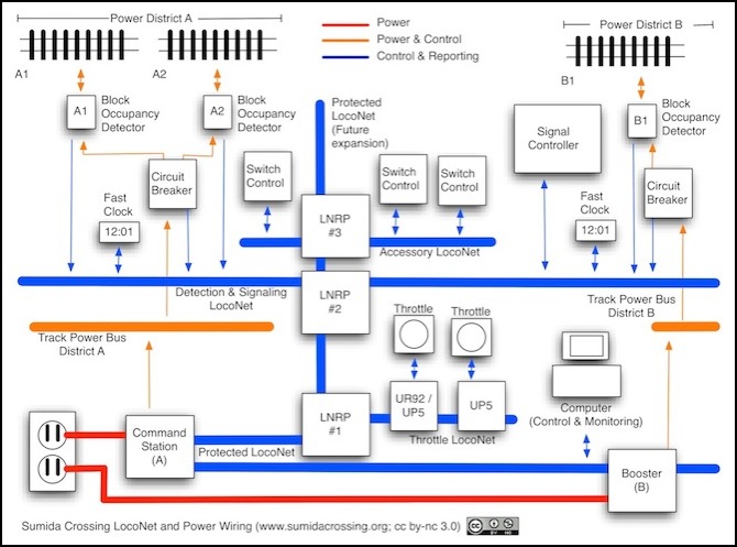
Sumida Crossing LocoNet
Note that the ordering of the isolated LocoNets created by the LNRPs doesn’t really matter. The above diagram shows the Throttle Loconet closest to the Command Station, but it could just as easily be the last one in the chain.
