


Arduino Knobs
17 April 2016 01:01 Filed in: Electronics,Basics
This is one of those “interim posts” I mentioned at the beginning of the year, posts where I don’t have something yet in a state where I can really talk about it, so I focus in on one detail that’s been taking a lot of my time, as a form of update. But today’s topic, rotary controls for computer-based systems, is a generally useful one, so I don’t think you’ll count this post a waste of time. At least not if you are interested in this aspect of the hobby.
A rotary control, or knob, is a control that can select a continuous range of states arranged in a circle, such as the volume knob on a stereo. Any rotary control can also be laid out as a linear one, simply by straightening out the underlying mechanism (they have to be designed that way, but often are). In schematic diagrams, a linear symbol is typically used to describe either kind, since from an electrical perspective they are identical.
In model railroading the most common application for this kind of control is a throttle. My first power pack, an ultra-cheap kit pack from Tyco, had a linear control (actually it was rotary inside the box, but the lever sticking out the side looked linear to me). Later, my first good DC power pack (my MRC 501, which you can see on my Power Pack Testing page) used a knob, albeit a simple one.
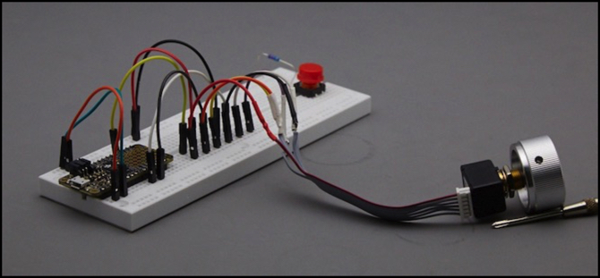
But today, I need a continuously variable control for a digital system, an Arduino to be specific. And yes, it’s for a throttle, but I’m not going to talk about the actual project I’m working on, as it’s still in the early design stages and there’s nothing much to say yet. Instead, I’m going to talk about the various options for this one control, and then go into more detail about the one I’m using, seen in the photo above attached to an AdaFruit Feather M0 Proto (a type of Arduino) for testing.
In the Beginning: Resistance is… Suboptimal
My oldest power pack uses a rheostat, as most did back in the 1970’s. A rheostat is nothing more than a variable resistor inline with the circuit. At the low setting, resistance is high, and most voltage is dissipated (as heat) in the resistor, so output voltage is low. At high setting, little or no resistance is present, and most voltage goes through.
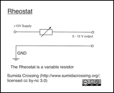
A rheostat works ok in analog circuits (I won’t say well, they have issues), but it’s a pretty poor choice for more complex circuits. First it’s terribly inefficient, wasting most of the power it uses as heat. Second, the voltage loss is current dependent, following Ohms Law: V=IR, where R is the variable part of the control, and V is the output. You’ll get different voltages depending on the current. In model railroad applications, this became obvious as motors became more efficient, and drew less current. Throttle knobs that used to work well, didn’t provide the same kind of speed control for newer motors.
About the same time as motor technology improved in the 1960’s and 1970’s the transistor throttle was becoming affordable. And rheostats don’t work very well with low-current control circuits. The solution was the potentiometer, commonly called a “pot”. This, too, is a variable resistor, but one where the output is from a wiper separate from the ground, intended to be connected to something that draws essentially no current, such as a transistor (or the input to an analog pin on a microprocessor, but we’ll get to that). What the wiper does is measure the voltage at the location it is set to, which can vary from full to none, just as on the rheostat.
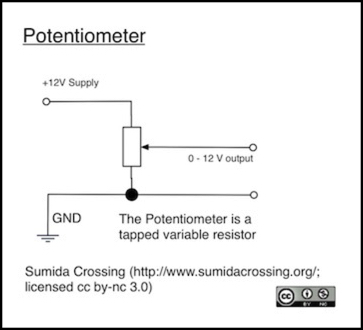
The benefit of the potentiometer is that the full resistance, often 10,000 or even 100,000 Ohms, is applied at all times. This means power loss through the resistor is fixed and very low (for 12 volts, a 10K Ohm pot dissipates just 1.2 milliamps). And because current is fixed, the output is uniform. A transistor takes that tiny output and amplifies it (that’s what transistors do, amplify), either directly in the case of a simple DC power pack, or less directly for more complex circuits.
Potentiometers have three primary characteristics: taper, resistance and “linearity”. Taper can be one of severals forms, which I’ll discuss more below. Resistance is usually some value between 10K and 100K ohms, although the reality often varies +/- 20% from the rated value (which affects nothing except the wasted power). Linearity is a measure of how evenly the resistance changes over the range of motion, and values around 1% are typical.
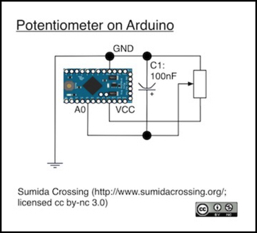
Connecting a pot up to an Arduino is simple. You connect its + and - contacts to the VCC and GND pins on the Arduino, and the variable tap output to an analog pin set as an INPUT. At low resistance, all 5 volts goes through, and analogRead will return 1023 (or close to it), at high resistance very little goes through, and it will return zero.
Although the Arduino sees this as 1024 discrete steps, that’s just how digital circuitry works. What’s really coming out is an analog value from 0 to 5 volts (or to VCC rather, which usually isn’t quite 5.0 volts).
Now truth be told, neither the rheostat nor the potentiometer are continuously variable, they just appear to be for all practical purposes. What’s really going on is that the wiper is moving from one point on a highly-resistive wire wrapped around a cylinder or bar to another point. Because of the wrapped structure, that next point is some distance further down the wire, so resistance increases in a step. There are other ways to make these that do have a continuous (or at least more continuous) variation. Typically this is expressed as an output smoothness or linearity specification, and a typical value is around 1%, improving to 0.1% on more expensive pots. For a 5V control, this means that accuracy is never going to be better than about 1,000 steps anyway, and in a typical potentiometer, it’s probably closer to 100.
Unless you have a really good ADC and a very good pot, there’s probably no effective difference between a 10K pot and a 100K one, and I usually use 10K pots when I need one.
Potentiometers are fundamentally analog devices, with moving wipers rubbing along some resistive structure. This means that variation isn’t quite uniform (that output smoothness noted above) and that there is the potential for analog noise as the control is moved. A key form of that is “bounce”, where the wiper sticks or jumps ahead as the control moves, or even loses contact entirely (causing a brief 0 volt reading). As a result, when using these with digital systems, some form of de-bouncing is needed, just as with simple switches, except that now the output is more complicated than a simple on/off result.
Debouncing a potentiometer can be done using electronics or software. With electronics a resistor-capacitor structure (an RC filter) is a typical solution, and since you already have resistance in the pot itself, a common solution is just to put a 100 nanoFarad (0.1 MFD) capacitor between the tap output and ground (as shown above; locate this as close to the Arduino input as possible). This is probably the best solution, as it will remove electrical noise found in the signal from external sources (any wire is an antenna, and will pick up both RF energy and noise from nearby wires by induction, and there’s a lot of RF noise anywhere near digital circuitry).
With software, some form of “is this what I expected?” test needs to be performed, or else the value read needs to be processed in a “filter” algorithm to smooth out variations. If you search the web, you can find a number of discussions of the best way to do this. Simply keeping some kind of rolling average of multiple samples can work, although there are more elegant solutions. I won’t go into those, as pots aren’t really the best answer if you care about precision.
If you hook up a potentiometer to a simple program that reads the pot and prints the value every tenth of a second or so, you’ll see that the number jumps around even if you aren’t touching the pot at all. That’s electrical noise, likely the limitations of the Analog/Digital Converter (ADC) circuitry inside the chip. If you turn the knob, it’s not likely you’ll get a simple change from say 54 to 55, it’s more likely to jump by a few values, and how much will vary.
loop() { int val = analogRead(MYPIN); Serial.println(val); delay(100000);}A note here: breadboards really suck for testing this kind of control, because the pins in those slots have variable resistance, simply moving the wires will cause values to jump around (I saw errors of up to 50 steps on the one I was testing). That’s a poor representation of how a finished design with a soldered connection will work.
Pots aren’t a bad control, and if you only need a fairly coarse output (say 20 to 50 steps) they’ll work fine. Getting more out of them is something of a battle though, and even with a good pot, it’s going to be hard to get a lot more. Pots are cheap, however, a good one will only set you back a few bucks.
When using a pot, you have a choice of “linear taper”, which has the same change in resistance at the high end as at the low end, or “audio taper”, which changes resistance less at the low end. Some people like that in a throttle, as it has better fine control at low speeds, where you most need it. Of course if the pot is input to a microprocessor you can get the same result with linear taper and some processing, and you can probably do it more precisely. In general, linear taper is preferable for microprocessor controls.
Requirements
So, pots are okay, but they’re a bit limited. Is that a problem? It depends on what you are doing.
I’m using it as a throttle. In practical terms, I doubt I can perceive more than a few dozen steps in train speed. In the early days DCC used 14 steps, and people saw that as a problem. Later 28 step decoders were introduced, and that’s probably good enough for most applications. But the actual DCC protocol allows up to 127 steps (0 and 2-127, for arcane reasons), so for a throttle designed for use with DCC, maybe aiming for that as a goal would be a good thing.
There’s another aspect though, precision. Ultimately, there are human hands on the control, and those can only turn a knob with a limited degree of accuracy (and as we get older, or consume more coffee, that accuracy gets worse). So at low speeds, where control is most important, perhaps we want a larger turn of the knob to result in a smaller change in throttle setting. This is essentially the software version of the audio-taper pot. If you have 28 steps and want the knob to be limited to a bit less than a full rotation, then perhaps your looking at 280 degrees equated to 28 steps, or 10 degrees per step. But maybe for steps 0-10 you want to use 15 degrees each, with steps 11-27 using about 7.5 degrees each.
A little bit of math (270 / 7.5) says that you need a control with 36 steps over 270 degrees to achieve that, which means at least 48 steps per rotation, just to achieve 28 step throttle accuracy. A similar calculation for 126 throttle steps says that a control with about 216 steps is needed. You can probably make a pot provide 48 steps (that’s an increment of 21 between steps on a 0-1023 scale), but you’re unlikely to get anywhere near 216 steps (an increment of 4.7 per step) consistently.
You can compromise, and a pot could be made to work, even for 126 steps, and you probably couldn’t tell the difference. After all, we’ve been using pots on model railroad throttles for more than 40 years and people have been generally happy with them. They do have the benefit of being inexpensive, and there are enough other parts to a throttle that saving pennies where you can isn’t a bad thing.
But I’m something of a perfectionist. I’d like to get those 216 steps. Is there a way to do it? Yes there is, but it comes at a cost in both money and complexity. I’ve been doing some investigating, and I think I’m going to spend the extra money for a high-resolution control for my throttle knob. And that’s what I want to describe today.
Encoders
The solution is a rotary encoder. As with pots, they also make these in linear form if you like levers or, as with my old Tyco power pack, you can attach a lever to a rotary control. What’s an encoder you ask?
If you are an electronics hobbyist, you are probably most familiar with encoders from servo motors and related control systems, as an encoder is often used with motors or axles to determine position or speed. Model railroad hobbyists who have used sound decoders for steam locomotives may be familiar with the encoder wheels that are used to time the “chuff” sounds to match cylinder position, and something very similar is used inside the housing of a rotary encoder.
In brief, an encoder can be made in several ways, but all of them basically create pulses as a shaft turns (or a lever slides along a track). Sometimes these have added circuitry to count the pulses or determine direction, other times the raw pulses are output and its up to you to figure out what’s going on.
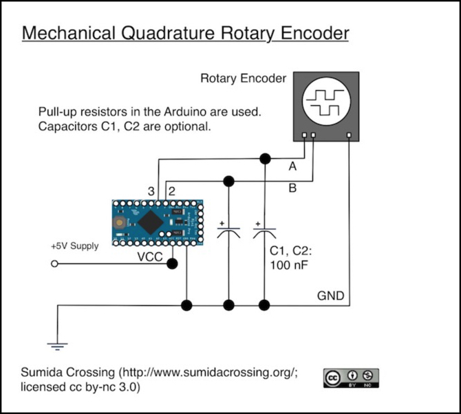
Encoders can be mechanical (and the cheaper ones usually are). These use a wiper moving between contact pads, so in some positions current flows, and in others it does not. Used with a pull-up or pull-down resistor, this provides a simple high/low value suitable for a digital pin on an Arduino, and as the knob turns, what you basically get is a square wave. Usually there are two outputs working together, and I’ll come back to that, but for now I’ll just mention that the two pulses provide a “quadrature” encoding of the motion, and that encoder of this form are called mechanical quadrature encoders or mechanical incremental encoders, since what they tell you is if the position is incrementing or decrementing, and how quickly, but not what the current position actually is.
Mechanical encoders are relatively cheap. Not as cheap as a pot, but we’re still talking only a few dollars. They’re limited in accuracy, often having only 12 or 24 steps per rotation (some have more) and they’re subject to mechanical keybounce from the contacts, so there’s the debouncing issue. But since the output can be read by a digital pin, a simple filter capacitor can again be used to deal with this.
The other options are non-contact encoders. These use active electronics (inside the knob assembly) to sense the turning encoder wheel without touching it. These are available in either magnetic or optical forms, and in practical terms it doesn’t matter which you use (magnetic ones are better in extreme environments, but that hardly describes a model railroad).
This circuitry has to be powered, but these encoders can provide higher accuracy and more steps, with values of 128, 256 or even 1024 steps available. Because the sensor is not based on physical contact, these last much longer than mechanical ones, with lifespans measured in millions of turns. They also cost correspondingly more, tens of dollars to over one-hundred. Accuracy and longevity do not come cheap.
These can be designed in the quadrature form, or to use a serial interface to return a binary number encoding a position around the dial, from zero up to the number of steps, wrapping around to 0 if you keep turning the knob (encoders usually allow continuous rotation, although some have stops to prevent that). The serial form is called an “absolute” encoder.
Encoders can also have additional outputs. An “index” or Z output goes high (or low) at one specific location, marking the “zero” point on the encoder. Some encoders will also have pins to indicate direction, although this can be calculated from the A/B pins on a quadrature decoder or by comparing sequential positions on an absolute encoder. Some encoders output the inverse versions of each signal as well, so both can be read for an additional error check.
Interrupts or Polling
There are two ways to read the A/B outputs from the encoder, polling it frequently to check the values of the two pins, or using interrupts. A standard Arduino only has hardware interrupt support on pins 2 and 3, so it might seem that you’d use all of your interrupts for one encoder. However, it is possible to read both pins when triggered from one (see second example on this page), so you could use pin 2 and some pin other than 3 for the first encoder, and pin 3 and some pin other than 2 for the second.
Use of interrupts is superior to polling for quadrature encoders, as with polling it’s possible to miss a pin change and lose track of direction and speed. There are a number of libraries available for dealing with quadrature encoders, see this page from the Arduino Playground site.
The clever bit about the quadrature encoder is that the two pins have their on/off states staggered, as shown in the image of the encoder in the diagram above. This allows the two pins to provide four states: HIGH/HIGH, HIGH/LOW, LOW/LOW and LOW/HIGH. From any state, only the two “adjacent” states can be reached in one change, and which you reach tells you the direction of rotation. The fourth state signals an error condition. Thus from HIGH/LOW, both HIGH/HIGH (decrement) and LOW/LOW (increment) can be reached, but LOW/HIGH would indicate that a step had been missed. This set of four values is known as “gray code”, although it’s simply an ordinary binary progression.
If you are using a 256-state encoder, and you need to correctly track motion of up to two turns per second, then both pins must be read approximately twice every 4 milliseconds to be sure of capturing all state transitions. This is within the capabilities of an Arduino, even without interrupts if carefully programmed. Moving to 1024 states, the pins must be read every 488 microseconds, which is possible but doesn’t leave much time for the Arduino to be doing other things, and makes the risk of missed states fairly high if interrupts are not used.
Absolute Encoders
An absolute encoder is one that reports the position of the encoder as a multi-bit binary value. Typically this will wrap to zero as the knob passes the index position. A 256-state encoder would report position as 8 bits. Encoders larger than 10 bits are uncommon, but do exist. Multi-turn absolute encoders also exist, which report the number of turns in addition to the position within the current turn.
As you may imagine, reporting a binary value in a serial bit stream requires somewhat more circuitry than a simple quadrature encoder. Additional information may also be reported, such as direction of motion or speed. Most absolute encoders report using some form of Synchronous Serial Interface (SSI), a fairly simple bit-stream with well-defined start and stop indications, driven at a speed supplied from an external clock, with reports initiated at the request of an external controller. Depending on the encoder, SSI can operate at speeds up to 1.5 Megabits (333 ns clock pulse width, or one bit every 0.67 microseconds). However, most can also be read at much lower speeds.
And, just to make life simpler, it really is possible to read these at high speed (1 or more Mbps) using either an SPI interface or an RS-422 serial chip (SSI is based on RS-422 clock and signal structure). Arduino’s lack RS-422, but they do support SPI. However, individual controllers will send more or fewer bits, both due to the resolution of the encoder (e.g., 8 bits for 256 steps, 10 bits for 1024 steps) and for additional information such as a parity bit or flags showing direction of rotation, error conditions, or other purposes. So a library supporting a specific model of encoder may not work for other encoders.
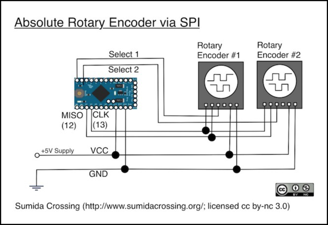
In the above diagram, two encoders are connected to the SPI bus (pins MOSI for the data and CLK for the clock), and each has a dedicated select line. The SPI lines require pull-up resistors (provided internally by the Arduino), and an encoder is selected by setting its “select” line to LOW. Because the SPI bus can easily operate at the full speed of an SSI signal (1 Mbps or more, depending on the encoder) a single Arduino can easily keep up with several encoders read a couple of times per millisecond with plenty of capacity left over to do other things. Thus for high-accuracy encoders, this is the most efficient method to use.
Note that not all encoders have a select input, and if not then the SPI bus would need to be dedicated to that one encoder.
While I haven’t tried this with two encoders, I do have it working with one. I’m using a Bournes EM22A series magnetic absolute encoder with 1024 steps designed for 3.3V microprocessors (part EMS22A30-C28-MS6-ND, US$43.15 from Digikey),. However I’m doing this on a Feather, which is why I need a 3.3 Volt version of the encoder (Feathers operate on 3.3V), so I haven’t been able to test it on an ordinary Arduino, as all of mine are 5V models. And the timing is critical, at least on this model. When I had too long a delay after pulling the select line low, I missed the first bit from the encoder. It’s possible that this wouldn’t work on an Uno.
I ended up with this encoder because I wanted a panel-mount model with a 1/4” shaft and with at least 256 steps, so I had multiple values per throttle increment (allowing me to ignore random position changes due to vibration moving the knob) and in the 3.3 Volt realm there aren’t a whole lot of absolute position encoders available, and this was the easiest to find.
Reading an SSI Encoder
The code to do this (on a fast M0-based Arduino, anyway) is remarkably simple, since Arduino’s standard SPI library can be used (just include SPI.h). This is a quick example, cut down from my full test program but verified to work. It reads the encoder once per second and prints out the position and the two error flags. There are some other bits not used that are returned by the decoder. To use it, the encoder needs to connect its DO pin to MISO, Clock to CLK and CS to the select pin (as well as the 3V VCC and Ground pins) as shown above. The MOSI pin must also be reserved for SPI use. Although it’s not connected to the encoder, the SPI library will attempt to send data over it.
In the photo at the top of the page, the black and white jumpers are MISO and CLK respectively, and the yellow is the select line.
Between the beginTransaction and endTransaction statements the SPI bus is configured for this ecoder, and interrupts that would allow the bus to be used for other devices are blocked, so it’s important to do only what is necessary between those.
#include “SPI.h” #define CS_PIN 5#define EM_CLOCK_RATE 1000000Lvoid setup(){pinMode(CS_PIN, OUTPUT);pinMode(CS_PIN, HIGH);SPI.begin();} void loop(){uint16_t bitsReturned;int position;boolean flagLIN, flagCOF;SPI.beginTransaction( SPISettings( EM_CLOCK_RATE, MSBFIRST, SPI_MODE1 ));digitalWrite(CS_PIN, LOW); // start readbitsReturned = SPI.transfer16(0); // send 0, which is ignored, read first 16 bits returneddigitalWrite(CS_PIN, HIGH); // done, de-select the encoderSPI.endTransaction(); // release the busposition = ( (bitsReturned >> 6) & 0x03FF);flagLIN = ( (bitsReturned >> 3) & 0x01);flagCOF = ( (bitsReturned >> 4) & 0x01);Serial.print(“read: “);Serial.print(position);Serial.print(“, errors: LIN: “);Serial.print(flagLIN);Serial.print(“, COF: “);Serial.println(flagCOF);delay(1000); // wait a second before doing it again}Note: if you cut and paste the above, you’ll need to fix the quotes. My web software turns them into curly quotes and the compiler doesn’t like that.
The two flags checked will be true if there’s some kind of error. It’s also a good idea to check parity for the number read (parity is computed across all 16 bits including the parity bit), and to do two reads in quick succession and ignore any that don’t match, to get the highest quality of response.
Although I didn’t check the other flags in this example, there are actually four flags related to hardware errors in the encoder (COF, LIN, INC and DEC). Bournes doesn’t document these very well, but this same set of flags shows up in datasheets for other kinds of encoders, and probably relates to a specific signal processing chip being used to read the magnet positions. COF is a signal processing overflow flag, LIN indicates a problem reading the magnetic field that can probably only happen if the magnet has been repositioned (which shouldn’t happen inside a sealed unit) and INC/DEC indicate that the magnets have somehow become too close or too far from the sensor to be read, again likely impossible unless the encoder is disintegrating. It’s probably a good idea to check all of these flags and treat any of them as a likely sign that the encoder has suffered physical damage (from being dropped or similar).
There is one flag that isn’t an error: OCF (“End of offset compensation algorithm”) you can test this similarly to the other flags but with a bit shift of 5. While Bournes doesn’t say so, again from datasheets for other encoders this is a “valid data” flag (if set to 1, then the position reported is valid). My observation is that this bit is always set to 1 on reads that don’t have parity errors, so that seems to be true.
You shouldn’t see any errors from parity normally, as that would only happen if electrical noise had hashed the signal briefly. You will see two sequential reads differ, but usually this is because the knob was turning and they just happened to catch the position counter incrementing by one. While “conventional wisdom” from what I’ve read on the Internet is to read twice and discard mismatched answers, I think with this encoder reading once and checking OCF (not COF, that one’s an error flag) for valid data after verifying parity would be sufficient.
With the specific encoder I’m using, clocked at 1 MHz, a read takes about 39 microseconds (including setup and post-read cleanup) so two sequential reads use about 80 microseconds. In practice, even with aggressive turning of the knob, at worst about 10% of my reads failed the matching sequential read test and ignoring those reads didn’t affect the program’s ability to keep track of throttle changes. And examinging them missed ones (with print statements), they all seemed to be cases where the encoder had incremented or decremented position by one, meaning that I was just unlucky and caught the encoder as it moved. However doing two reads does waste time I may want to use for other things, so unless I come up with a good reason, I’m likely to switch to one read.
For a human-controlled knob that’s returning an absolute position number, you don’t need to check too often because for it to change enough to reach a new value takes at least 500 microseconds, and usually a lot longer. And in my throttle it needs to change by about 8 values to change the throttle setting, so you can actually go a couple of milliseconds between reads normally, and probably a lot longer without being noticeable if necessary. Which means that the processor spends very little time dealing with the control, leaving it free to do more productive things.
One final comment. An absolute encoder returns a position number from 0 to N, but the knob can rotate continuously (N+1 becomes 0 and the cycle starts over, and similarly 0 - 1 = N). That’s useful in a number of ways, but it makes a poor throttle if turning it down past zero can suddenly raise the speed to full throttle.
So to make use of it, I use absolute position to compute a relative change from last position (both step count and whether it was up or down). With that, I can compute a throttle step (simply divide movement count by 8 to get the number of DCC steps changed) and when the throttle goes to 0, further downward changes are ignored. Similarly, when it gets to step 126 (top DCC step number) further increments are ignored. The “divide by 8” part also means that it takes a full turn of the knob to go from zero to full, and that any vibration moving the knob less than 8 positions is ignored. My processing of encoder inputs is actually a little more sophisticated than that, but that’s the heart of it.
That does mean that there’s no consistent “zero” position for the throttle knob, so having a knob with a line on it would be very confusing, but as you’ll see when I finally get around to describing my throttle, that’s not an issue for me.
Summary
A $40 absolute encoder is much more expensive than a potentiometer, which can be had for a couple of dollars. What you get for that, provided you use an absolute encoder, is a control that still provides a position, and provides it faster than analogRead can read a pot, and with much higher accuracy. If that’s what you want, and I think I do for my application, then it’s worth the cost.