


LCC III - Messaging
Mark Twain is alleged to have once opened a letter with the statement "Please forgive the length, as I did not have time to write a shorter one." He didn't actually say that, but he gets credited for it. That happens to Twain a lot: he has so many good quotes, people keep attributing others to him. The actual originator of the quote is apparently Blaise Pascal. Regardless of who said it, I know exactly what he meant.
This post took a long time to write. It would have taken longer, but I gave up trying to shorten it.
Back in October I started what I thought would be a relatively easy, if perhaps a bit long, post on messaging in LCC. I was trying to cover it in detail, explaining how the ideal LCC had to be adapted on CAN Bus. That proved distracting and I put that material aside to just focus on the basic messaging capabilities of LCC rather than the implementation on CAN Bus, at least to the extent I could.
In the process of doing this, I've managed to chase myself in circles more than a few times. The LCC standards are very confusing, even by NMRA standards. We're talking about documents written by volunteers rather than professional standards-writers, and generally without a whole lot of editing. I've been reading NMRA standards for more than 25 years and I'm used to having to work at it to puzzle out the actual meaning. But still, the lack of clarity in the LCC documents is exceptional.
I'll detail problem areas throughout this post, but it basically boils down to things either being omitted entirely from the documents or being covered in one of the other technical notes than the one you’d expect. And there's a fair bit of using two different names for the same thing and, conversely, using similar names for two different things.
The revised post is about messaging in LCC and what you can do with it now, and additionally I'm coming at this as a review of the LCC standards, not anything external to them. The OpenLCB team has written a lot of words about OpenLCB, and that’s often helpful, but what matters in a standard is what's actually incorporated in it, either directly or by reference to or citation of an external document.
I've used some of the OpenLCB documents to flesh out my own understanding when I found problems in the LCC documents, but I've tried to come at this in the way that someone fresh to LCC as an NMRA technology would. So I’ve kept my focus clearly on what is and isn't defined by that set of standards, and how people working only with those could interpret them. There's probably a lot of context written down that I never found, and more locked up in the heads of the developers, but most people wouldn't find that.
NMRA standards, incidentally, are the "S" documents. These state requirements (are "normative" in standards language). Although LCC isn't using them yet, the NMRA also has Recommended Practices documents ("RP"), which despite the name are a lesser form of standard. Both of those need to be formally approved and can state requirements, although RP requirements are kind of a lower level than S requirements. Technical Notes (TN) are not standards, and you'll see the statement that they're "not normative" in the LCC TN documents. TNs are commentary on why a standard exists, or how it could be (not must be) applied. That's an important distinction to keep in mind.
As I've pointed out a number of what I see as problems in the standards here, I feel it important to say that overall I'm still very impressed with LCC. Most of the problems are documentary in nature rather than conceptual. Documentary problems can be fixed, mostly, even after hardware ships. What event and datagram messaging provide is very powerful. The two-button event learning process is a very clever and user-friendly interface to a potentially very complex system. And with Memory Configuration, there's a foundation for even more user-friendly usage.
This is far better than DCC with all its CVs and requirements for users to understand binary numbers. Using JMRI with LCC is still somewhat computer-geeky, but that's a JMRI problem; we can't blame LCC for that. LCC devices on their own can easily be built to be “plug and play”, and that I expect will lead to some very simple entry-level devices suitable for the “Christmas Tree” and 4x8 layouts, something this hobby needs if we’re to attract the next generation.
Still, all that said, I'm disappointed at how much of a mess this is. I thought reading DCC standards was hard, but LCC is a whole new level of hard. Hopefully most modelers will never have to read them to make it work.
Overview
Messaging in LCC today refers to three capabilities:
- Events: short broadcast(*) messages reporting status or simple commands (like "I'm activated" or "train detected")
- Datagrams: longer directed messages for passing a more complex message ("set throttle on 2828 to speed 87")
- Memory Configuration: for reading more complex status or setting complex configurations (things with many values)
There are other kinds of messages: an entire class of "addressed messages" exists that provides basic functions and is also used by the above messaging systems, as well as a planned (but apparently not much fleshed out) stream capability. I won't go into those today as they're just a distraction.
* I'm using "broadcast" very loosely here, see the discussion of Events below for more detail.
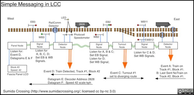
The diagram at the top of the post shows how the first two could be used with a collection of simple nodes to build a system where signals react to occupancy detectors and turnout settings. I’ll say more about that diagram in the discussion below.
But before I get into messaging, I need to touch briefly on three topics: reliable message transfer, Message Type Identifiers and Node Identifiers.
Reliable Message Transfer
A key part of LCC is the concept that messaging is reliable. That's actually called out by a comment in TN-9.7.3.2, Datagram Transport, section 3.2 (why there and not in some place more fundamental is one of those things that annoy me, but that is where it's said). It's also implicit in events being one-time "state change" reports rather than repeated "current state is" reports. As far as I can tell, only Event transport would be affected by unreliable messages (datagrams have error recovery built in), which makes putting the statement that it's important in TN-9.7.3.2 even less comprehensible.
In the initial release, that dependency is somewhat obscured by the fact that only CAN Bus is supported, and unlike other network technologies CAN Bus guarantees message delivery. Well, sort of, a node can still be overloaded and lose a message it received due to buffer issues, but that's already unlikely and going to be less likely as hardware gets even faster with time.
That assumption of reliability is woven into how Event Reporting is designed. Lose it, and events assuming it won't work correctly. I'll say more about that in the Events section.
One problem here is that network technologies in general do not provide for reliable message delivery. That's something you have to add on. Most networks today are IP-based even when using technologies like Wi-Fi and Ethernet, and in an IP network you get reliability by using TCP atop IP (hence the common name TCP/IP). But IP also uses unreliable transport for lots of things, like phone calls, video and even the name lookup that happens when you type a URL into a browser. And neither Wi-Fi nor Ethernet, used alone, are reliable transports. Applications have to be designed to either use reliable transport, compensate for unreliable transport, or accept that sometimes message are lost.
Using LCC across technologies like Wi-Fi has a fundamental assumption that there will be a reliable transport layer added between the LCC we have today and the underlying system. Without that a signaling system may lose the fact that a block has become occupied, a clock tick that triggers the noon bell on a church may be lost, a toggle switch may fail to throw a turnout, or having thrown it fail to show the new position on a control panel. Individually those are small things, and in many cases a human will see the problem and fix it, but collectively they're the difference between LCC being useful and being an annoyingly erratic system.
Since the requirement for reliable transport is not defined in a standard, in fact there isn't even a standard where it could reasonably be defined, and there's no TN about the need for reliability, I'm concerned that future designers, or third parties trying to fill perceived gaps (e.g, bluetooth radio support) might implement systems without a reliable transport layer, leading to erratic behavior. That's a relatively minor concern since it's easy to correct, but it's one of the things about LCC as defined today that worry me.
Or maybe the TN is wrong, and reliable transport isn't intended, but if so the guidance on how to use events is wrong too.
Message Type Identifiers
A Message Type Identifier, or MTI for short, is a number that uniquely identifies one message form as being different from another. For example, there are separate MTIs for a full-capability node to announce that it is ready (MTI 0x0100) and a node limited to the "Simple" set of capabilities to announce that it's ready (MTI 0x0101).
MTI IDs are normally written in hexadecimal (that's what the "0x" on the front means), so they contain numbers from 0 to 9 plus letters from A to F. So, for example, the Producer/Consumer Event Report MTI is 0x05B4.
There's a deeper meaning to the numbers that make up MTIs, which causes them to be longer than mere sequentially-assigned numbers would be, but for today just think of them as a unique number that separates one kind of message from another.
One of the complexities of MTIs is that they need to be sent in messages, but they're bigger numbers than they really need to be. And CAN Bus in particular is starved for space in message frames (a topic for another day). So what happens is that the long MTI (up to 17 bits today, called the Common MTI) gets chopped down to 12 bits for use in CAN Bus. This shortened version is called the CAN-MTI.
You'll see this in the LCC documentation, with the Common MTI written with an extra digit (e.g., 0x0100) and the CAN-MTI written with just three (e.g., 0x100). It's the same MTI even though it's a different number (well, in theory it's a different number, today most MTIs aren't using the high bits anyway so we're throwing away leading zeros and both end up being exactly the same number; in the future more will be different numbers in the two forms).
Depending on context, you may see references to both, and it can be confusing if you try to understand why the CAN Bus portion of a document is referring to 12 bits but the number you think goes in there has more. The thing to remember is that the Common MTI (four digits) is used by LCC in general and the CAN-MTI (three digits) is a variant form used for LCC on CAN Bus.
In today's post, all further references to MTIs will be to full-size Common MTIs.
Nodes, Node Identifiers and Unique Identifiers
What is a Node, anyway? I mentioned back in the first post in this series that a node was "a tiny computer plugged into a CAN bus". I probably should have said "LCC network" instead of CAN Bus there, since there will be nodes that have nothing to do with CAN (e.g., wireless throttles). But even that's not strictly correct.
A "node" is really a source or destination for messages. That's usually a single standalone device (e.g., an occupancy detector, or a box containing several occupancy detectors), but consider control software running on a computer. You might have a track diagram produced by one program, a software throttle (or throttles) produced by others, and a software based fast-clock produced by a third. Those could all coordinate somehow to be one node, but it might be simpler just for each of them to be its own node, and LCC supports that kind of operation. When a single device contains multiple nodes these are referred to as "virtual nodes" (per TN-9.7.0.1, the Glossary), but functionally each acts like a normal node so there's really no distinction. A node, real or virtual, is a node, and all nodes act the same (with lots of options).
While some messages, such as Events, go to every node, other messages are sent to just one node. For that we need a way to identify a node. As is usual in networks, this is done by giving the node a number, called an "address". However LCC prefers to avoid that term, and use "Node Identifier" (or "node ID") instead. In LCC, a node ID is one use for a six-byte number called a Unique Identifier (defined in S-9.7.0.3, Unique Identifiers). Every Node ID is a Unique Identifier, but a Unique Identifier need not be used as a Node ID.
Six bytes is 48 bits, or an integer from zero to 281 trillion (2.81x10^14), which is a lot of IDs. But most of these are "reserved" today, with only a tiny subset defined for initial use. Others will be added, and a node has to be prepared for any one of those 281 trillion IDs to be used.
Now we come to one of the really strong points of LCC: unlike DCC, you don't have to tell a new node its address. It should have come from the factory with one that's guaranteed to be unique world-wide, so you can just plug it in. No more typing in numbers with keypads or setting tiny switches. This isn't a novel idea: Ethernet has been doing the same thing for 35 years: manufacturers pre-program every Ethernet interface with a unique address as it leaves the factory. LCC manufacturers will do the same thing.
Formally, a Node ID could by shipped blanks, and have a programmable address or use switches: TN-9.7.0.3, Unique Identifiers, section 5.10, explicitly states that nodes may come without an ID. And section 2.5.5 implies that this can be done by kit builders. The standard doesn't actually require manufacturers to provide IDs for every node they sell, it just says that if they do those IDs have to be unique. I expect nodes will come with them; it's easy enough to do and manufacturers who don't do it that way will get treated harshly by reviewers.
Unique Identifier Assignments
Numbering nodes when you make them is easy. Every manufacturer with a registered DCC Manufacturer ID gets 24 bits worth of unique identifiers for their own use. That's 16 million Unique IDs, which is probably more than they need even though Unique IDs can be used for things other than Node IDs.
There is also a separate set of 16 million for electronics hobbyists, called the DIY range. This exists because there's a DCC manufacturer ID for DIY use. In DCC it didn't matter if these were not unique, since they were just information reported by a decoder (a comment, effectively). In LCC, nodes addressed using these are not guaranteed to be unique since two people could use the same ID number for something. That's not a problem if you use your nodes at home (presuming you don't have any DIY nodes made by a friend), but it means that this range can't be used by hobbyists who sell their home-made nodes. See below for a solution for that group.
JMRI also has a manufacturer ID, with a prefix allowing it to define up to 16 million nodes. Again, these are going to be the same for every JMRI out there, so if you have two JMRI systems on one layout, you could have a conflict, although it looks like the software tries to avoid that (the implementation isn't guaranteed to be unique, but conflicts are unlikely).
JMRI's documentation says that the node ID assigns one byte of the Node ID from the system's IP address and two from the "process ID" so that multiple JMRI's on a layout can be distinguished. My limited experimentation confirms that each time I restart JMRI it uses a new ID based on its "Manufacturer Specific" block (prefix 0x020112). However, this means that a JMRI node without an IP address is very likely to be in conflict. That may seem unlikely, but I actually have plans for embedded JMRI control systems without addresses; a non-LCC project I'll talk about in a future post.
Even potential conflict here shouldn't be an issue as the node ID is only used with Events (aside from possibly some support in Decoder Pro for writing memory on devices; I can't tell what protocol that's using), and you can manually assign any event ID to a device on its control panel. As we'll see below, the actual node ID of the sender or receiver is irrelevant in event messaging. And LCC has a mechanism to deal with conflicts, although I've no idea if JMRI implements it.
It does mean that when working with JMRI, it is important to assign event IDs from devices on the layout to objects in JMRI, and not the other way around. JMRI doesn’t provide any means to do it the wrong way, but this is a rare case of asymmetry; normally you could just as easily associate an event from a control panel to a device, as an event from a device to a panel.
In the event that the current set of IDs the NMRA has is insufficient, they also have a block of 16 million IDs, ostensibly for future manufacturers although the NMRA could later decide to use it differently.
MERG, a UK group “promoting interest in the application of electronics & computers to all aspects of railway modelling” has several reserved blocks for use when communicating with their CBUS nodes across an LCC network. These include a block of 16 million for "Node ID translations" plus three additional blocks of 65,536 IDs (16 bits, or 64K) each for CBUS events and future use.
And finally, members of NMRA and MERG each get 256 IDs (8 bits) all their own that are globally unique, based on their membership number (expressed in bits). As we'll see below, that means that every NMRA or MERG member also has 16 million unique events they can use with no fear of conflict. Well, strictly we (I'm an NMRA member) get 255 IDs. A note in TN-9.7.0.3 section 2.5.1 states that a zero value for that individual shouldn't be considered a valid ID.
This incidentally, is the kind of ambiguity in a standard that makes my head hurt. As mentioned earlier, a TN isn't part of the standard. Reserving a value of zero ought to be a statement in either an S or RP document (and LCC badly needs some RP documents), with the TN perhaps clarifying why it was reserved. Putting the requirement here means that a modeler can use zero in the last byte of their assigned range for a node ID, but if they did, it might not work correctly because someone else treated zero as reserved. And both of them will be "correct". Ouch.
Additional blocks of potential IDs are reserved for future assignment, possibly to uses other than LCC (OpenLCB uses the same ID range, and could be used for things other than model railroads).
Other Users of Unique IDs
When I first examined this standard, I thought I found an oversight in the set of reserved blocks for IDs. After more reading, I see that the problems I saw have intended solutions, it just wasn't made clear in the S documents that those existed. Assignment authority for the solutions seems to have remained in OpenLCB rather than being an NMRA responsibility, which is a bit odd, and the lack of NMRA involvement is part of what confused me. Perhaps the NMRA didn't want to own that process, but if so that seems to me to be a failure to fulfill their responsibilities as standards-keepers. But as long as somebody's doing it, and the NMRA recognizes them (which their publication of the standard implicitly says that they do), that's what really matters.
The potential problems stem from two things: first, not all nodes will be made by traditional manufacturers. Someone with an Arduino and a CAN Bus shield (or some similar hobbyist microprocessor and the necessary CAN chips) can put their own node together. Where does its Node ID come from?
And second, Unique IDs are used in events, and there are some situations where having them centrally-assigned may be desirable. How does a club or show organizer get a set of IDs to use for that? There are some other problems here, but I'll skip over those for the moment and discuss them when I get to Events.
As it turns out, there are two solutions defined in S-9.7.0.3, Unique Identifiers, that cover these and other scenarios.
The Self-Assigning Groups class of unique identifiers (section 5.5, prefix 0x03) currently only lists NMRA and MERG ranges, with a comment that future groups can be defined under the same prefix. According to TN-9.7.0.3, this is intended for membership organizations, where a prefix is assigned to the group, and members within the group get a smaller block (typically 256 IDs per member). So while NMRA and MERG are the only groups defined today, additional membership organizations can be added in this category, apparently on request. No actual mechanism for that is defined, and it appears that OpenLCB rather than the NMRA controls such assignments, although that isn’t clearly stated anywhere I could find.
This I see as a problem. If this is truly for other membership groups then there needs to be a well-defined process for those groups to follow to apply, and it probably ought to be happening under the auspices of the NMRA. But there's nothing defined here, and whatever is intended, it doesn't appear to be the NMRA doing it.
Consider the DCC Manufacturer ID code as a contrast. This assigned number and its process is defined in S-9.2.2, Configuration Variables for Digital Command Control, since it is a value reported by a DCC decoder via a configuration variable. The actual list is published separately, but is formally Appendix A of that standard (i.e., it's an "S"-series document) and contains the statement "Manufacturers not on this list shall apply to the NMRA Technical Department for the assignment of a unique manufacturer ID". That's simple, unambiguous, and formally part of the standard. The same approach should have been used here, but wasn't. There's nothing in S-9.7.0.3 (or any "S" document) explaining the process, even TN-9.7.0.3 only says that "Unique Identifier ranges can be assigned to these groups", without explaining by whom or how.
There's another method, targeted at individuals, the Specifically Assigned by Requests block (section 5.7, prefix 0x05) This also applies to companies that for one reason or another don't have an NMRA-issued DCC Manufacturer's ID. This neatly covers non-traditional manufacturers as well: individuals or small groups like clubs that make small-run circuit boards and sell them online. They can get their own block, and issue one node ID for each board they sell (perhaps on a sheet of paper, if the board is sold in kit form to be assembled by the purchaser). This one's a bit more organized, and allows assigning both one byte ranges (256 IDs) and two-byte ranges (64K of IDs), and there's a web page for requesting such a block from the OpenLCB designers, or at least the 256 ID form. I don't know how well the process works as I haven't tried it (I don't need any Node IDs at present, and I'm an NMRA member so I already have 255 anyway).
At present there is only one 16-bit prefix assigned, and that's for Railstars, a now-defunct manufacturer of model railroad electronics.
Note: in S-9.7.0.3 there's a prefix reserved by OpenLCB in the Specifically Assigned by Request block for 24-bit ranges as well, although none are assigned as yet.
Even here, there's a problem with the assignment process. The standard says that both 256 and 64K ranges can be assigned (and there's implicitly the intent to also support 16M ranges), but the web page only supports requesting the smallest size (or so it says). Maybe the form just needs a pull-down to select the type of range requested (256, 64K, 16M Assigned by Request or a 16M Self-Assigning Group block), although it would be good to have more clarity on what requirements, if any, affect which class you can request. Can I declare my layout a self-assigning group because it has a team of operators some of whom build stuff for it, and request 16 million IDs? There ought to be some kind of criteria involved that says a group of size X or smaller normally only qualifies for a certain size. Presumably there is, but it's not formalized or communicated here, and so right now there's no way to request anything other than a 256-ID range, although one company seems to have managed to get more.
Leaving aside the problems of implementation, between them these two systems cover all of the gaps I thought I saw in the standard. If the Self-Assigning Groups method isn't the best solution for a small club,they could always request a 64K block through the Specifically Assigned by Request process (assuming they can figure out how to do that) and delegate the last byte to up to 255 members. That would probably work better for small clubs with tens of members at any given time than requesting 16 million IDs via the Self-Assigning Groups approach. At worst, they might need to request another block of 64K in a decade or so, since they can't recycle any of the IDs when former members leave. In any case, there are solutions for assigning IDs to several different scales of groups, and that's what's most important.
Having got all that out of the way, let's get to the actual topic of today's post: messaging.
Events
The Event Transport protocol, defined in S-9.7.3.1 Event Transport, supports the reporting of "events". There are several capabilities defined by this protocol, but first, what is an event?
An event message (formally, a Producer/Consumer Event Report, or PCER, with MTI 0x05B4) is a report that something happened. This could be a toggle switch on a control panel being thrown, a block-occupancy detector sensing a train for the firs time, or anything else that is easily represented as an "it just happened" statement.
This is a little subtle: if you think about an on/off toggle switch, with two events ("on" and "off"), the events don't mean "turn some device on" (or "off"). They mean "the switch was placed in the 'on' position" (or "off"). What some other node does in response to this news is entirely up to it. Maybe the switch is on a CTC panel and means "traffic direction is east" when placed in the "on" position, and all eastbound signals will clear while all westbound signals will go to "stop" when they see the "on" event.
Formally, the standard doesn't actually require that events be one time. Their interpretation as "state transitions" (one-time actions) rather than "states" (a condition that persists) is from TN-9.7.3.1, section 1 and TN-9.7.0.1, Glossary. There's nothing in an S document that says you only send the event report once per event occurrence. The standard can equally be read as having the occupancy detector emit the event periodically as long as the state created by the occurrence persists, like every 3 seconds (I'm assuming the timeout interval for S-9.7.3 section 3.7 here, but it could be some other interval), with one event for "I'm occupied" and another for "I'm not occupied". That's apparently not what was intended, but it's what was written.
And here's where reliability comes in. If Event Transport is reliable then events can be about state transitions as described ("switch #7 was just thrown"), but if events can be lost, then for reliable behavior they have to be repeated and reflect states ("switch #7 is in the 'thrown' position", pause, "switch #7 is in the 'thrown' position"...). It's a simple choice: reliable transitions or unreliable states; pick either, but unreliable transitions aren't a good option.
If you only write event-creating devices that work with your own event-using devices, you can do it either way. But for interoperability between manufacturers there has to be agreement on how events will be treated. This is an ambiguity that really needs a clearer statement to allow that agreement, both of the need for reliable transport (or not) and of the intended usage of events (or perhaps both usages are valid, but if so that should be said clearly).
Event Sharing
Events are a global message, with a single message sent to all interested receivers. This means that they aren't sent to a specific recipient, but rather are broadcast for any node on the LCC network to receive if it wants them. This is a very efficient way of dealing with things happening, because there may be more than one receiver interested.
Consider as an example a track occupancy detector. When occupied (an event) the signals on either side of its block turn red, when clear (a separate event) they turn green. At the same time, a distant control panel shows the occupied/clear status of the block (it may also compute and display the signal indications). All of that is triggered by one event (out of a pair of them) sent by the detector, with at least three nodes (two signals and a panel indicator) registered as interested in it.
For events to work, two or more nodes need to agree on the meaning of an event ID. This typically means taking the Event ID number from one node and saving it in the other (or multiple others). There are a couple of ways this can be done: you can have one node "teach" the other via a process using two buttons on a node, call the teach/learn process or the two-button process. Or you can have a central system handle it, using either the "teach" mechanism or the more general "download configuration" mechanism described in S-9.7.4.2, Memory Configuration.
Event Registration
Once a producer and one or more consumers agree on the event ID, they still need to work together. Assuming I'm reading section 6 of S-9.7.3.1 correctly, the node sending an event (the Producer of the event) is supposed to report to every node on the network that it is a producer of that event when it starts up (via the Producer Identified message, which comes in three forms with MTIs 0x0544, 0x0545 and 0x0547).
Because other nodes might be connected later, it is also required to respond if another node sends a broadcast message asking "who produces event X?" (the Identify Producer message, MTI 0x0914). Even simple nodes are required to process the latter. This way, every node on an LCC network can know if there is a matching producer out there for events it cares about. Simple nodes don't have to listen for the answer, but the intent here is probably that they just assume that there is a producer, and if not do nothing. A more complex node might take some action if a producer can't be found. This could be a simple notice to the user, such as a turnout sending a datagram to display "no producer for 'set diverging route' found" on a control panel. Or a system could switch to an alternative method, such as a control panel using a built-in Fast Clock if a standalone one isn't available elsewhere on the layout.
Similarly, a node using the event (a Consumer of that event) needs to report to everyone that it's using the event (via Consumer Identified, which also has three forms, with MTIs 0x04C4, 0x04C5 and 0x04C7) although simple nodes can ignore the message when received. Both of these are marked "Simple=N", but I read that as meaning that simple nodes aren't required to process these messages on receipt; they're still required to send them (per section 6).
The latter is important, as it is basically a requirement that nodes register their interest in an event. As the standard notes, this allows gateways to filter events for which no nodes on a segment have registered interest, reducing overall traffic. This is very important for bandwidth-constrained network technologies (e.g., wireless) and for very large layouts. It’s also vitally important for making LCC work on non-CAN Bus networks, as events would likely not be forwarded by a gateway unless it knew of an interested node beyond it.
In networking terms, this makes Event Transport a "multicast" protocol. Unlike a broadcast, which always goes to everyone, multicasts can be trimmed down to only go where they're needed in a large network, in order to reduce unnecessary traffic.
Related to this, TN-9.7.3.1, section 2.6, notes that an Initialization Complete message should cause receiving nodes to remove any registered interest by that node in all events. It also says that this is the only mechanism that removes expressed interest. There's no negative form of Consumer Identified. The reason for this is that gateways aren't intended to keep a list of who is interested in an event, only that some node on a segment at some time did so (which means that resetting a node and causing it to send Initialization Complete won't actually cause a gateway to stop forwarding the events it previously expressed interest in).
There’s a potential hole here in gateway design: if the default is to not forward events unless a node expresses interest, and nodes only express interest on a reboot, what happens if you wire up the gateway, or reboot it, after the nodes are powered on? There needs to be some way for a gateway to notify on-net nodes (including other gateways) “I just started, tell me what events you care about”. A gateway could be required to send something like an Identify Consumer message when it starts, but it would need a way to do that for “any” event. Maybe an Event ID of zero could act as a wildcard for that purpose and Identify Consumer could be used. But I don’t see anything at present, and this needs to be a basic “respond when you get this” requirement of every node, so it will be hard to retrofit in the future.
Event Ranges
Descriptions of Events often focus on simple on/off changes, but you can do a lot more with Events because producers and consumers can define themselves as producers or consumers of thousands, or even millions, of events with one message. This is done using ranges and the Producer Range Identified (MTI 0x0524) and Consumer Range Identified (MTI 0x04A4) messages.
Both of these methods use ranges based on masking. Masks produced ranges that are powers of two, so if you need 1440 events for a fast clock reporting each minute of a day, you actually need to report production of, or interest in, a range of 2048 events, as that's the next power of two larger than 1440. Both messages have the restriction that a node has to use more than half the events in a range, which is implicitly a requirement for contiguous event numbering for large numbers of events (half of a power of two is the next lower power of two, so if you skip even one you'll require the next larger power of two before you use half of it). As we'll see in a bit, there's something of an escape clause for this, and some event ranges can be sparse.
You can represent more complex things using a number of events. TN-9.7.0.4, Event Identifiers, gives an extreme example with a Fast Clock using one event per minute-hand tick. That's 1,440 events for one day, but they actually describe using 16 million different events (perhaps they want to allow every minute over a span of 32 years to have a unique event). Silly comments aside, ranges make using large numbers of events easier, and using large numbers of events provides a good way to solve some problems.
Source Nodes Don't Matter with Events
S-9.7.3, Message Network, section 3.1, notes that "All messages shall contain a source Node ID". But note that this does not state that the source must be communicated to the portion of the node processing the received message, only that it has to be in the message. In fact, TN-9.7.2.1, CAN Frame Transfer, section 1, notes specifically that CAN "does not provide any indicator of which node sent a particular frame". If the source isn't replicated in the data portion of the frame (and for events it is not required to be), then you don't know who sent it. Nor does it matter.
You can find out if a given node produces an event, but not if it was the one that just sent the event you received. Identify Producer can be broadcast to all nodes to ask "who produces X". And Identify Events has a directed form that can be used to ask a node what events it produces. This uses MTI 0x0968 (as opposed to 0x0970 for the global form of Identify Events), and this use is called out in section 2.4.8 of the associated TN. Again, this isn't something a node would need to do. It's unclear to me what either of these commands are useful for.
Similarly a node can't tell just one node "I'm interested in event X", but you wouldn't know who you had to tell anyway (the answer is "all gateways between you and any producing node", which isn't something a node can figure out).
The whole concept of events is that it's the event that matters, and the event (via the event report) is unique to one thing happening. There normally wouldn't be two nodes reporting the same event, but it's not prohibited and TN-9.7.3.1 section 2.4.6 specifically mentions that more than one node can respond to an Identify Producer message as producer of an event. A node using Identify Events to attempt to isolate one producer is probably doing something wrong. If there is more than one producer for an event, receiving the event from any of them should have the same result, and the Consumer shouldn't care who sent it. It's the event that matters, not where it came from.
As an example of how you might use this, consider a turnout that can be controlled from multiple panels using a CTC control system as shown below. With CTC, you throw a turnout by setting a lever to one of two positions and then pushing a button to transmit the state of that lever to the turnout. Multiple control panels could have their nodes configured with the same two events ("set normal route" and "set reversed route" to use CTC terminology).
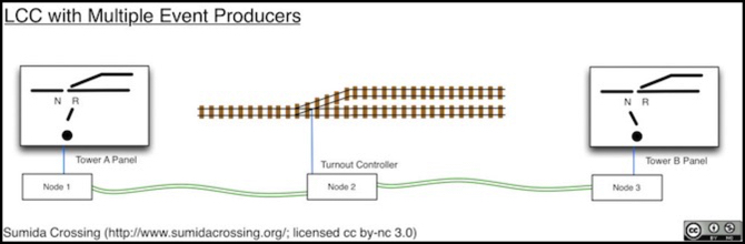
When someone pushes the button on the panel for tower A, the position of its lever (reversed) chooses which event its node will send. The position of levers on other panels doesn't matter. The turnout will react to the most recent event received, regardless of which panel sent it. And if the other panel sends the same or the other event a second later, it will react to that one too. And both panels will see the event sent by the other panel, and can update their "which position is it in" lights in response.
Notice that what is being transmitted is the “event” of the button being pushed with the lever in a given position. It’s not the state of the lever, or the push of the button, but their combination that makes the unique event. And the fact that Node 1 or Node 3 sent it is entirely irrelevant. The same combination on either panel results in identical events being received by Node 2.
Event IDs
What's contained in a PCER message (i.e., the event report) is simply an event ID, nothing else.
Event IDs are formed from six-byte "unique identifiers" (as defined up above in the section on Node IDs) with two more bytes added on the end. There are some special events, used for various control protocols, but for typical messages, it's a unique ID plus two bytes. However, it doesn't have to be the same unique ID that the node uses for its Node ID, although that's likely to be the default for most nodes.
Note: I'm not going into the well-known events here as there aren't many. There's a list of these published by OpenLCB. It's linked from TN-9.7.3.1 section 3.4, but the URL is bad. The actual document is linked off the specs page as a PDF (a second link there to an HTML page is also bad).
Note: this is another case of critical information not being formally part of the standard. Publishing it on the OpenLCB page is fine, but as we saw with DCC manufacturer IDs, that page needs to state that its list of well-known events is part of the standard, and it needs to be linked to (or referenced by) the S document, not the TN.
The fact that Node IDs are unique IDs means that every node automatically gets two bytes worth of events: 65,536 events that are globally unique and will never be issued to another node. But there are other unique IDs that can also be used to make event IDs. As an NMRA member I have 255 Unique IDs of my own, based on my membership number. That means that I have 16 million event IDs (255 times 64K) unique to me, that I can use on any node I want (store-bought or homemade, for use at home, at a club or on a temporary show network) without any concern that someone else would be using them.
This isn't actually formally defined by the standard. What it says is that event IDs can be formed from a "Uniquely Assigned Node ID" (note that it says "Node ID", not "Unique ID"), period. But TN-9.7.0.4, section 2.2 ("Intended Use") says that this can be any "Node ID address space assigned to you", not just ones configured on a node (which implies that they really meant Unique Identifier rather than Node ID). The TN isn't part of the standard of course, but it's a strong indication that S-9.7.0.4 section 5.1 means "Assigned Unique Identifier" when it says "Assigned Node ID".
And while Node IDs are specific to a single node, the event IDs associated with them (as well as those formed from other unique IDs) can be handed off for use by another node. Formally, this is called "learning", although some of the documents also refer to it as "teaching" the event.
Event IDs, in short, are unique 8-byte (64 bit) numbers based on 6-byte unique identifiers. They may be associated with an original node via its Node ID, or come from some other unique identifier, which could be the node ID of some other node. In any case, they are not necessarily being sent by a node using that identifier as its Node ID so you can't infer sender from event ID.
Because event IDs are "built in" to nodes based on their Node ID, the average person won't need to configure them, at least not as numbers. You can't completely avoid some work, as we'll see in the next section. As with node IDs being preprogrammed, this is a significant simplification for the typical user, and another strength of LCC.
Event Learning
Event learning happens via the Learn Event message (MTI 0x0594), which is sent from a node that already knows the event ID to all listening nodes that have been placed in a receptive state. In effect, the sender is "teaching" all nodes on the network that need to learn the event the ID to use. In fact, several places in the standard refer to this as part of the "Teach/Learn" process, and a few (S-9.7.3.1, section 6.5, TN-9.7.3.1 section 2.6.5, 2.6.6 & 2.7) refer to it as the Teach Event message.
Both producers and consumers can learn events to be used. And nothing limits the event to being used with the original meaning (it can only have one at a time, but that can change over time). In fact, nodes can "pass along" a learned event. Say, for example, you had two control panels that both needed to throw a turnout. Assume the first panel was taught an event produced by the turnout, the second panel can learn the event from either the turnout or the other panel.
It's actually never stated formally what happens when a node is taught an event, or at least I couldn't find it. Is it permanent or temporary? If it's temporary, then a node will need to be re-taught if it loses power, so presumably it's permanent (and all discussion seems to assume that). And this is implied by the one reference in TN-9.7.0.3, Unique Identifiers, section 2.4, that says they could be stored in non-volatile memory or jumpers (both permanent methods). But even the TN doesn't says it has to be permanent. This is one of those weakly-stated definitions that annoys me about LCC. Ambiguity is the last thing you want in a standard, as it's nearly guaranteed to cause a problem at some point.
Just to add some chaos to an already complex situation, S-9.7.3.1, Event Transport, section 6.6, states a requirement that a producer or consumer "contain a unique Event ID" when reset to defaults. Note that an ID that's been "passed along" via the Learn process is no longer unique, so this implies that the original Event ID can't be used after a reset and the node has to reprogram its default for every event used by every producer and consumer it has.
TN-9.7.4.2, Memory Configuration, section 2.4.19, actually goes into more detail on this, providing several possible implementations. This is another of those misplaced bits of guidance. Why is it in TN-9.7.4.2 rather than TN-9.7.3.1? That's because the latter is discussing the Get Unique ID command of the messaging standard rather than Event processing. They both seem to be discussing the same general concept though: events need to be "unique" after a reset even though you can't "call back" one you handed out before the reset.
This whole "unique after reset" concept seems very problematic to me. Renumbering event defaults is implied by the standard even if the process isn't detailed, so we can't just ignore it. I doubt it could be made to work in practice for all nodes (I'm thinking particularly about ones using large ranges of their 64K allotment. Even without that fast-clock example with 16M events I can come up with events needing tens of thousands of unique IDs in a range. I’m sure someone will end up using more than 32K for something, which prevents renumbering unless you assign multiple Node IDs just to allow for that.
The central problem here is that an event is an arbitrary number that means whatever you want it to mean, and the way Teach/Learn is structured it's completely possible for a modeler to take a unique ID and re-use it in ways that aren't unique. You can't prevent that if you allow events to be portable, and there is so much value in that portability that it wouldn't be a good idea to restrict event learning in ways that might try to control it.
But that can make managing a larger layout problematic, which is probably why they tried to ensure uniqueness in this manner. You really need to be using an entirely different event ID management approach to keep a large layout organized (e.g., programming event IDs from a central pool via the Configuration protocol). using the two-button process with dozens to hundreds of LCC nodes just isn't going to be practical.
Consider for example a turnout controller (an Event Consumer): A user buys the turnout controller, installs it, and then teaches its default "set to diverging route" event to switch #7 on a control panel (an event Producer). Later that same person rewires switch #7 to a lift bridge when the control panel is updated, and teaches the bridge motor controller (a different event Consumer) the event from switch #7 to use as its "raise bridge" event. That’s the even it learned from the turnout controller, so it’s now non-unique. Then when switch #7 is thrown, the bridge goes up and, if nobody updated the turnout controller to use a different event during the control panel update, the turnout also throws. At no time did they reset anything, so having "renumber on reset" isn't going to save you in this instance.
You could try to fix that by making learned events unteachable, but that simply restricts flexibility and won't solve the problem in every possible case. There is no way software can protect agains this kind of human error without a central authority managing event ID use, and LCC by definition does not require a central control system, nor should it for simple use cases.
Of course if you have a central system, it can use methods that ensure it's using "clean" (never before used) event IDs when it configures a device. The Get Unique ID command in S-9.7.4.2, Memory Configuration, appears to exist to support that.
And "renumber on reset" is a really bad idea in other contexts as well. Consider that fast clock with a range of 1440 used events I mentioned earlier. It's being used by a half-dozen throttles with time displays, several control panels, and a few special devices (the chimes on the model of a church steeple, a clock on a model sports stadium). Now assume you have a problem with the fast clock and decide to reset it (which is often the average person's response to any problem without an obvious solution). Now it's generating a whole new set of 1440 events that nobody is listening for, and you can either reprogram all of them (silly) or reprogram the fast clock to use the original numbers as if it hadn't been reset. In attempting to solve one problem, which the user may not have had, you've created an entirely different problem for them to fix by making events renumber themselves arbitrarily.
It's a lot better to have "reset" really be a reset, and put everything back to the way it was when it came out of the box. It may not be ideal for all cases, and a human can still do dumb things. But at least the behavior of a reset is predictable. But doing the sensible thing appears to be a violation of the Event Transport standard as presently written.
Transient Event Configuration
This is something that isn't really addressed by the standards, but particularly for shows and similar situations it probably needs to be.
Assuming event learning is permanent as implied above, once taught events are forever associated with one or more additional nodes besides the original one. That's a problem if you're setting up a modular layout at a show and need to share events between modules, but only for the duration of the show. When the module owners go home at the end of the show, they'd take any assigned IDs with them, and might end up teaching them to other devices and using them at another show. This magnifies the problem of portable events, but again note that since nobody is doing any resets, changing events on reset isn't going to do anything about it. Here you just have to assume that an event handed out for a show can never be handed out again, which is how the standard is written, but that places a burden on show organizers to keep a record of which have already been used. Want to bet on how long that paperwork is kept after a show?
Now this can be addressed with the Get Unique ID portion of Configuration Management that was discussed up above. Sure those IDs assigned to modules leave with the modules. So what, at the next show you just use a fresh set and all the “paperwork” is handled by a computer or node managing the pool. With 65K per unique identifier, it's not like you're going to run out. Well, not unless you are using a fast clock with 16 million events (remember that example?). Still, it's inefficient. Why not simply allow transient, refreshable, assignments as an option?
I think that's a gap in the standards that needs to be fixed. It would be helpful to have something like "Learn Permanent Event" and "Learn Temporary Event" messages. Temporary event IDs could be assigned by a control system, stored in RAM, prohibited from use in Teach/Learn, and forgotten by nodes when power was turned off (with the control system required to re-teach them if needed), or nodes could even be required to "refresh" them periodically by confirming their use with the original issuer. Meanwhile permanent ones would be manually assigned (the two button teach/learn method or via Get Unique ID) and stored in non-volatile memory for long-term use. This implies use of a control system with temporary events at a show, so that it can re-teach all of the needed events if there's a power outage mid-show, so it's not a solution for everyone, and maybe there are better ways to solve this problem. But that control system could be a simple LCC node: buy the node, program it from something that speaks Configuration Management with one or more Unique IDs for Event ranges, and then just plug it in when needed. It seems to me that transient layouts, which are definitely a large part of the hobby, need transient assignments.
The Messaging Example
At the top of this post is a diagram, which I’ll repeat here for ease of reference:

This shows how events and Datagrams could be used (I’ll ignore the datagram part for the moment). Here we have a set of simple nodes that control signals, manage a turnout, and detect block occupancy. This is all that’s needed to create a prototypical signaling system. I’ve assumed one detector node is also equipped with RailComm and a speedometer, but that’s for the datagram portion, which I’ll ignore for now.
Signal nodes have to keep a record of the current state of blocks (occupied or empty) important to their signals, based on the last event received. And they may also need to track a turnout, if one is in an adjacent block. Actually, to be prototypical they need to listen for events in two blocks in either direction, but I’m only showing two adjacent blocks here so I’ll discuss it as if that’s all they can do.
The signals here show red fro “next block occupied” or green for “next block clear”. Additionally, for turnouts we’ll assume a second head shows the status on the diverging line (similar to a “slow clear” or “diverging clear” in prototype North American systems). So in this example, the turnout is lined for the siding, which is empty so signal EB2 shows red-over-green to indicate that, and loco 2828 is occupying block 2, so signals EB3, WB2 and WB12 display red because of that. If the turnout was thrown to straight, then signal EB2 would need to show red-over-red since the block ahead was occupied (which is why the signal nodes need to remember the last event; it may not be relevant until something else happens).
Note that since events are one-time (transitions), Event A is only sent when the train enters the main line on the right, and if it remains parked there the event is not resent. And similarly, Event B was last sent when a train left the siding (or possibly at power up as an initialization activity).
Once LCC has a market, I’d expect to see signals like this as relatively inexpensive add-ons for beginner layout kits (maybe US$40 for a node with several cheap plastic signals) similar to the current Atlas signal system product, or even built into signals (like the current signals from Tomix).
More Complex Events
Events are (as noted in TN-9.7.3.1, section 3) a "many to many" relationship. More than one Producer can emit the same event. More than one Consumer can use it. One example, given in an OpenLCB description linked from that tech note, uses events for route selection. Each event is tied to one route, and when a switch is pressed to select that route, multiple turnouts process the event and move to different positions to create the desired route. That's one event per switch (a momentary "on" only, no "off") with several switches used together on a control panel.
You could also use that approach with a rotary switch (or software) controlling a turntable: event A sets the turntable to track 1, event B to track 2, and so on.
And clearly ranges imply the intent to do even more, and some of the examples mentioned in the tech notes confirm that. There aren't any standard examples today of such protocols, but there is one in development: the Time Broadcast Protocol, intended for use with either a fast clock or a real-time clock (which is just a 1:1 fast clock). This is available from the OpenLCB specs page as draft versions of both S and TN documents dated 2013. This isn't a standard yet, as it hasn't been through the NMRAs acceptance procedure, so building to it could be chancy, but it provides a perspective on how to use events intelligently in a more complex manner than simple on/off state changes.
This uses a set of four "well known event ID" values, as a six-byte prefix to define four clocks, each of which communicates months, days, hours, minutes and years as sets of events (years range from 0 - 4095 AD, in case your layout involves Roman Tin Mines with mine carts or futuristic anti-grav trains, presumably). The protocol also allows a manufacturer or layout owner to use their own Unique ID to define other clocks, if the basic four aren't enough.
It does this using four sets of events under the selected prefix: one for year (4096 events), one for month/day (366 unique events) and one for hours/minutes (1440 unique events), all part of a range. It's a pretty clever way to use multiple messages to encode about two million unique minutes into fewer than 6,000 events.
As presently defined in draft it requires a node to reserve a range of 32K events because it's been structured so the two bytes represent different things (e.g., hours and minutes). That creates a "sparse" range of events, less than 6000 used out of 32K, but it makes it much easier for humans to read the numbers: 10:47 AM is 10x256+47, or 0x0A2F in hex.
It would violate the requirement in S-9.7.3.1, section 4.7, prohibiting use of ranges that are less than 50% used, except for the qualifier there about "except when specified by another OpenLCB standard", which seems like cheating. Structured sparse event ranges are a good concept, and ought to be available to other users of events. But even with the huge quantity of available events, I can see the value in wanting to promote some degree of conservation there.
One nice thing about this approach is that specific times, like noon, are always represented by the same event, even on different days. That makes things like nodes that ring church bells at noon easy to implement, as they need only listen for that one specific event. And a clock-tower face controller need only listen for the hour/minute range of 1440 events.
The protocol as defined doesn't handle seconds, but a fast clock really doesn't need to. It could be extended easily with another set of 60 events for reporting seconds, or even 600 events for tenths of seconds, if desired.
Datagrams
Datagrams (defined in S-9.7.3.2, Datagram Transport) are multi-frame addressed messages that can transfer up to 72 bytes of data from the sender to a single destination node reliably as a single action using a Datagram Content (MTI 0x1C48) message. What's more, they can be linked together into an ongoing exchange using a "reply pending" attribute on the acknowledgement of each datagram.
Note: because 72 bytes is larger than a CAN Bus frame will hold, when sent over CAN a single datagram is actually broken up into a sequence of frames, transmitted and reassembled if possible by the receiver. But this detail is hidden from the program using datagrams. It sends or receives one datagram of up to 72 bytes, and either all of it gets through intact, or none of it does. Given CAN’s reliable transport, all of it should arrive.
Datagrams are addressed messages. They are sent to one destination, and any other node (i.e., a node that has a different node ID than the destination) simply ignores any it receives. On systems other than CAN, the other nodes wouldn’t even receive them.
Error Handling in Datagrams
When a datagram is received by the addressee node, the receiver is required to either reject the message (with Datagram Rejected, MTI 0x0A48) or acknowledge that it was received intact (with Datagram Received OK, MTI 0x0A28). There are three things that can cause rejections: the node doesn't handle the datagram sent to it, the node can handle it but not right now and it needs to be re-sent later, or the node received the message damaged and a fresh copy needs to be resent (there are a number of different error codes possible, but they boil down to variations on these three conditions). According to S-9.7.3 section 3.7 that response must be sent within three-quarters of a second (750 msec) after receiving the datagram. The sending node must wait at least three seconds (per the same section) without such a response before it assumes the datagram was lost and tries to re-send it.
Note that the last form won't ever be used on a CAN Bus: by definition a datagram can't be received damaged on a CAN Bus. If it was the damaged portion would have been detected by the CAN Bus reception system and the sender would resend it, well before trying to reassemble the datagram and pass it up to the receiving program. This error correction system being built into datagrams means that datagrams are themselves a reliable transport method (unlike events) and don't need an underlying reliable transport layer on systems other than CAN Bus.
Notice that the Received OK message doesn't include information about whether some action the datagram requested was actually performed successfully or not. Consider a datagram from a software or wireless throttle to a DCC command station that is requesting that a value be stored in a CV on a decoder. The user types some keys, hits "Write CV" and the datagram is sent. The command station receives it, sends back the Received OK message, and then attempts to perform a Write operation to the decoder. Some time later that operation either succeeds or fails.
The technical note suggests (section 2.4.2) that the reply pending bit can be used to perform a delayed update on the state of such an action. So, when the command station receives the datagram it sends back the Received OK message with Reply Pending set. The throttle gets this, and knows to wait for an additional datagram. The command station does its update of the CV, which either succeeds or fails, and sends back an appropriate message in a new addressed datagram. The throttle, waiting, takes that response and uses it to display something to the operator, such as "Ok" or "Error" on its LCD.
Now if getting that status response later doesn't matter, that could be the end of it. The node that set the reply pending bit might never send one, and the waiting node might not care unless one arrived. If the user doesn't get any response, they'll just try again.
But some things do need to be handled more cleanly than that, and the node sending the Datagram Received OK with the reply pending bit can also set a timeout field with value N of 0 to 15, meaning to expect a reply in 2^N seconds, which can be up to 546 hours (2^15 seconds). What the other node does at the end of that time isn't defined. It probably would send a "hey, where's my update?" request, and get back a fresh pending bit with an updated timer if the operation was taking longer than expected, but that's up to the specific program using timeouts to define.
Datagram Content ID
The first byte (actually one or more) of the data field of a datagram has a special meaning. This is the Content ID "byte". According to TN-9.7.3.2, Datagram Transport, section 2.4.1, the intent is to use this to identify different interactions, so that two nodes can have multiple separate long-term interactions going on in parallel. For example, a command station could be transmitting messages to a central station to be logged or displayed to a user at the same time that it's doing a CV update for a wireless throttle. There needs to be some way to separate the "this is a message" datagram from the "this is your CV update response" datagram since either could be received ahead of the other.
Unfortunately the values possible in this are nowhere defined in the standards, nor does a quick online search turn up any non-LCC documents from OpenLCB. S-9.7.3.2 says that it's up to the developer of a protocol to define the ID (and list it in their standard). When Memory Configuration (S-9.7.4.2) uses datagrams (it can also use streams) it sets the first byte to 0x20, which apparently is the identifier for memory transfer datagrams, but it's the only one I could find defined in the standards.
Even more confusing, TN-9.7.0.1, Glossary, refers to this first portion as the Datagram Protocol ID and says it can be 1-7 bytes in length, although typically only 1 is used. Although there's a table of protocols in S-9.7.3, this is for distinguishing things like datagram from stream, not for defining protocols within the datagram protocol itself.
TN-9.7.3.2, section 3.4, does mention that the Datagram Content IDs can be either 1 byte or 6 bytes in length where the six-byte form is a Unique ID controlled by the protocol designer. And it further says that the intent here is that some special first byte ("certain values" of the Content ID) signals that either a two-byte field or six-bytes of unique ID follow. But it doesn't say what those values would be. A "separate spreadsheet" is mentioned, but as was the problem with node IDs, it's not even referenced by the standards, and certainly not a part of one. And this is all in a TN anyway, not part of any standard.
With a bit of searching, I did turn up a copy of the missing list of special first bytes in PDF form on an OpenLCB page. This states that the special bytes are 0xEx for two-byte protocols and 0xFx for six-byte protocols. It's unclear what the "x" means, perhaps only the first nibble matters. This lists 0x20 for "Configuration" along with five other pre-defined bytes for things that aren't presently part of LCC.
The lack of any formally defined set of Datagram Content IDs in an "S"-series LCC document is a glaring hole in the current standards. Without this, manufacturers could just make up their own bytes at random. The standard doesn't allow that, but since it simply says that the author of a protocol must define their own bytes it can be read as permitting it. That certainly wasn't the intent, I'm sure, but it's what they wrote. Again, a table like this ought to be formally incorporated in an "S"-series document, with some words about how one requests a new ID. That doesn't preclude publishing the page separately with a link from an NMRA page, the way Appendix A of the DCC CV standard is published, but you can't simply publish it separately without a linkage or anything that formally makes it part of the standard.
Datagram Example
Referring back to the example graphic at the top of the post, one of the detector nodes uses datagrams to communicate with an LCD panel. While I could have used events, I’d have needed to use about 12,000 to cover all the possible DCC addresses and speeds. And very few things need to know about speed or DCC address (likely just a couple of control panels), so they can each ask for a separate datagram to be sent without creating an unnecessary load on the network.
Here when a train passes the detector RailComm is used to query it for its DCC decoder address. At the same time, the locomotive breaks a beam from an LED to two separate photodetectors, and the delay between those two is used to calculate its speed (in scale mph or kph). These two could be sent in one datagram, but to allow some devices to track only one I’m showing two here.
In this example, only the panel node has asked to be sent the datagrams, so when a train passes through the detector, the two datagrams are sent to the Panel node at the same time the Event is sent to everyone. The panel node unpacks the data, and writes it to a small LCD panel mounted to the fascia. Notice in particular that the Panel node just has to be somewhere on the LCC network; it doesn’t need to be anywhere near the detector node. It could be on an overhead fascia or a distant control panel, well beyond the distance practical for direct wiring.
And if you have more than one panel that needs the info, both can request the detector node to report to them. There’s likely to be a limit on how many, simply because the detector node has to keep some state about both, but it can easily be dozens of panels.
Memory Transfer
I’m not providing an example of this, because it’s both self-evident (configuring nodes) or completely dependent on things outside of LCC at this time (i.e., Digitrax could easily make nodes that could be configured by their control system, but there’s no real way to allow a different vendor to configure their nodes at present). There’s some groundwork laid for future multi-vendor configuration systems, but it doesn’t appear complete yet.
S-9.7.4.2, Memory Configuration, isn't just about configuring memory in nodes though. It's actually a protocol that enables the creation of commands that can do a variety of things, including direct memory transfer of bulk data. A large set of the currently defined commands essentially define a Memory Transfer protocol, and I'll describe that here, but that's not all it does, and it's clearly extensible and can be used for other things in the future.
Memory transfer isn't really a separate messaging type, although functionally it acts like one. What it really is, is a protocol that uses datagrams (and in the future streams) to move blocks of memory as messages. The name refers to "configuration" since that’s probably the first use for it, but it's really more flexible than that. Two nodes could use it to exchange structured information (e.g., a table of data being shared between the two). Or nodes that need to perform a bulk transfer of some kind can use it to write directly to a large buffer (a more efficient method than sending smaller chunks of data).
Memory transfer by whatever name is a powerful tool. A node may have up to 32 sets of information (called "address spaces"). Each set can contain up to four gigabytes of information, far more than is likely to ever be needed. As we've seen so often in the past, it's hard to predict how much memory we'll need in the future. But 4GB seems like a whole lot for an LCC node, and it's much better to err on the high side, so this seems like a really good choice to me.
As a potential example of that, consider a lineside speaker system used to create appropriate background noise (car horns in an urban area, burbling streams in a rural one, etc). The sound files for this could be made available online, and downloaded via a simple App from a computer with an LCC connection. Using memory transfer to load tens or hundreds of megabytes that way is going to be simpler then using datagrams directly.
The Memory Configuration protocol has its own set of commands. The first byte of a datagram containing 0x20 identifies it as a Memory Configuration message, and the second byte identifies the command. So, for example, "read from configuration memory" begins with 0x2043 because 0x43 indicates a read from address space 0xFF, which is the configuration space. There's a whole bunch of these commands, and I won't get into the details.
Each space may be marked read-only or read/write, although as we'll see shortly that can also be implicit in the definition of the space.
Streams (which aren't standardized yet) are required to read/write more than 64 bytes of information as one action. Datagrams can be used for 64 bytes or less. However, you don't need streams to write larger spaces than 64 bytes. A memory space could be written/read iteratively as sequences of datagram writes/reads, and there is a "Lock" command (0x2088 followed by your node ID) that can be used to ensure that such sequential access is done without interference. Just lock the space for your use, write your data as chunks 64 bytes or less in length, and then unlock it (by sending 0x2088 followed by zeros).
This could still be problematic (imagine if half a configuration field is changed and something happens to prevent the other half; you’d probably need to do a reset to clear the lock), but used with care it seems workable. The associated TN has some comments regarding configuration that I interpret as cautions about how this mechanism ought to be used for reliability.
Three of the address spaces are pre-defined (all are optional):
- 0xFF (255): Configuration - always read-only
- 0xFE (254): All memory ("all" may be a subset of the real all)
- 0xFD (253): A node-specific writeable configuration space (defined by the node creator)
Note that two of those have fixed definitions of their read/write status. The "all memory" one does not, but I'd be very surprised if any node designer actually marked their memory as completely "writeable".
It's somewhat hidden, but there are actually two more pre-defined address spaces, 0xFB and 0xFC. These are referenced in section 4.14 of the standard (the Get Configuration Options Reply command).
- 0xFC (252): "Manufacturer part of Abbreviated CDI"
- 0xFB (251): "User entered part of Abbreviated CDI"
This is the same "ACDI" referenced in passing in S-9.7.3.4 Simple Node Information and S-9.7.4.1 Configuration Description Information, although neither gives the full form of the acronym or says much about what it means. TN-9.7.3.4 does give the full form of the name. The actual definition turns out to be in TN-9.7.4.1, Configuration Description Information. Since that's not normative, it appears that there isn't any standard definition for it. This would seem to me have been better off as an RP document (just the schema and related requirements, not the full TN).
The other memory spaces are more ambiguous. It appears that the other 251 are available for any node designer to use as they like without restriction, with none reserved for future standardized use by protocols, and without any need or ability to reserve others for future standards. That seems like an oversight to me.
Node Management
The Memory Configuration standard also incorporates several basic functions related to node operation and management that I'd have expected to find in some other place as applications layered above memory transfer. Included here are:
- Get Unique ID (0x208C) & Reply (0x208D) - return up to 8 event IDs guaranteed unique
- Reset/Reboot (0x20A9) - cause the receiver to reboot
- Enter Bootloader (0x20AB) - cause the receiver to begin updating its firmware
These are here because they're done using the memory configuration command mechanism, but this is not an obvious place to look if you come to the standards and ask yourself "what do they say about node or event ID management?". A standard about copying data is not where I'd think to look for that. I'd expect to find Get Unique ID defined in Event Identifiers or Event Transport, and the other two in an RP or S on node configuration and management, for example.
Summary
There are some other odd bits scattered around, like the Simple Node Information protocol, but I'm not going to get into those. This post is long enough as it is.
In the end, I feel a bit disappointed in LCC. And yet I'm still quite hopeful for the future. A lot of work has obviously been done to create a flexible system that isn't going to be obsolete in a decade, one that has a focus on allowing modern technology to be extended in the future, and also that allows it to be used to hide the messy details from users. That's all good.
But as I said at the beginning, even as NMRA standards go, these are really, really, hard to read, and badly structured in parts.
I've already touched a couple of times on the ambiguity around some of the special numbers used in LCC, and how those need to be more formally part of the standards and have defined mechanisms for acquiring new ones.
The second thing LCC really needs is a good edit by a professional tech writer or editor, to fix problems like the "Learn" message sometimes being called the "Teach" message, or "Datagram Content IDs" also being called "Datagram Protocols IDs". Not to mention details that matter to a standard only showing up in a tech note explaining a different standard, or critical details like the structure of the Datagram Content ID being entirely omitted from the standard and only referenced in passing in a pair of tech notes.
Some more detail on defining how message transport is to be made reliable on inherently unreliable communications systems like wireless is desperately needed. Until that is done, I strongly fear that at some point someone will realize that it's an impossible goal, and LCC will have to redefine how events are used from the ground up.
There's also a strong risk that "unofficial" extensions that simply ignore the lack of reliability will be made (e.g., for LCC over Bluetooth or something), and become de-facto standards in the absence of anything else. Solutions doing that won't be "conformant", but if they're the only solution out there, their flakiness will taint LCC anyway.
Some basic functional RPs are needed. Protocols such as the current draft Fast Clock spec should be an RP, since someone could do a fast clock differently. One use of RPs is for when there is more than one viable method, but you want to call out one as a recommendation for use when there's no reason to do something else. This kind of definition is particularly important, as it provides a common language for basic devices to use and promotes interoperability between manufacturers, which is one of the main goals in an NMRA standard, perhaps the most important one.
Beyond fast clock, an RP for a throttle / command station train control protocol would be particularly useful, explaining how "cabs" interact with DCC (or other) command stations over LCC. Throttles could always do other things (like listen to the fast clock or throw turnouts), but there needs to be a common language for "set throttle to 90%", "engage brake", "ring bell", "sound horn" or other typical train control functions you'd send via DCC. Again, this should be an RP because vendors may want to do their own more sophisticated things with throttles that aren't compatible with it, but having a basic train control RP makes it more likely that everyone's throttles will as least be able to do the basics of running a train on any command system that speaks LCC. There are hints in the current LCC documents that someone was thinking about this, but they're all hedged around with words that basically say "but we're not going to do it this way, probably" now.
Finally, they need to take some of the things recommended in tech notes or that aren't written down (but are probably in someone's head) and write a few RPs to fill in those gaps. What should a node do when starting up or rebooting? How should common devices like signals or turnouts be controlled and report their status? How should a modular club use events for temporary layouts? That kind of basic guidance will go a long way to ensuring that simple LCC devices all play nicely together.
With work, I think LCC will be very good. But it definitely needs work.
This concludes my series of posts on LCC, at least for now. I’ll probably write more once there’s some hardware on the market to play with. And I have some CAN shields for Arduino and may try doing something there (although the current state of the Arduino library does not encourage me). But for now, I’m turning my attention to another project I’ve been thinking of for a number of weeks. More on that sometime soon.