


A Short History of Transistor Throttles
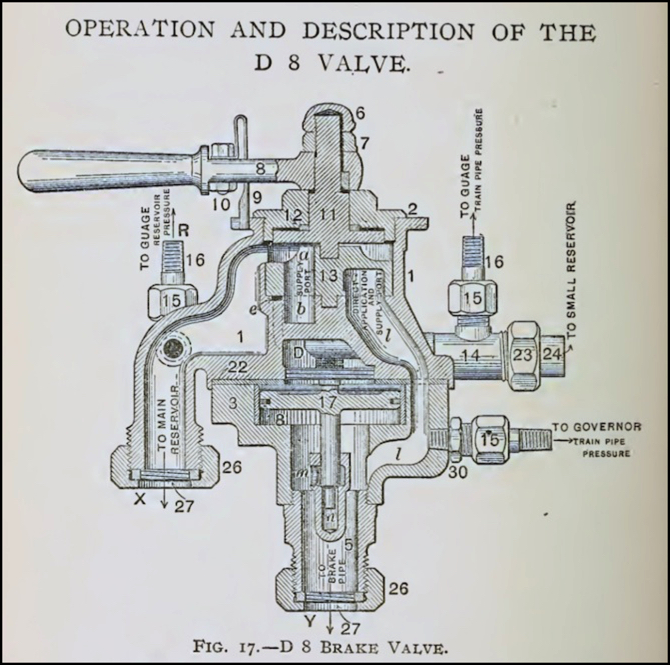
Westinghouse D8 Air-Brake Valve Assembly (from a c. 1900 textbook)
My interest in the design of transistor-based DC throttles (aka Power Packs) for model railroading ended up causing me to pick up the DVD set of Model Railroader back issues (henceforth identified as MR). While US$200 seems like a lot, I think it was well worth it, if only to satisfy my curiosity. And it works out to less than US$0.30 per issue, so in a sense it’s a bargain. I also dug up a copy of Peter Thorne’s 1974 book Practical Electronic Projects for Model Railroaders (mine is the third edition of 1975), which has a number of throttle circuits, including one using an SCR. This book can go for rather high prices online, but I found mine at a train show last week for the cover price of US$3.50; quite the bargain.
Early-on electric model trains were run with car batteries (some early ones used AC motors with AC from a transformer instead), first apparently at 6 volts but by the 1930’s DC motors were apparently designed for 12 volts even before cars switched to the larger batteries, requiring two batteries placed in series (per MR August 1934 article on the use of DC power). DC at 12 volts was more than enough to run small motors, and early throttles were little more than a variable resistor (rheostat) to reduce voltage for slower speeds, and a Dual-Pole, Dual-Throw (DPDT) switch to reverse polarity for direction control. Often a “knife” switch would be used for the reverser, which could be left in a central “off” position to disconnect the throttle from the track.
But modelers weren’t very satisfied with these. DC didn’t allow for smooth low-speed operation, and “jackrabbit” starts with a minimum speed over 10 or even 20 scale miles per hour (16 - 32 kph) made for poor switching operations. Plus, modelers wanted to model the behavior of real trains, with simulated momentum and realistic braking action.
This led to designs for more sophisticated “throttles” and ever more complex designs as electronics technology improved. Some of the results did a fairly good job of replicating the real behavior of trains, right down to simulating the performance of air-brake systems similar to the one in the diagram at the top of this post. It’s possible some of this took place before the transistor was introduced; vacuum tubes could have been used for similar things. However, nobody appears to have published their experiences with these, so it seem likely that little or nothing was done until the transistor came along.
The development of the low-cost transistor in the late 1950’s made more complex throttles accessible to a hobbyist with a relatively minor amount of electronics skill and for a reasonable price, and the next decade was a time of rapid change, with evolution continuing into the 1970’s. By 1980, interests had shifted towards running multiple trains using command control systems (the precursors of DCC), although the roots of those went back further. And even in 1980 you could still buy rheostat throttles, although they were definitely behind the times by then. None of these technologies fully displaced the others. The transistor has in fact soldiered on into the era of digital controls, and you can still buy transistor throttles today that aren’t too different in principle from those designs of a half-century ago.
The Transistor Throttle
The transistor is, in essence, an amplifier. It takes a small signal and uses it to control a much larger one. Small signals are what you get from a potentiometer, so these are often used as the throttle knob. The predictable current of a potentiometer, which doesn’t vary with load the way that of a rheostat does, made this a superior control to the older rheostat throttles. And it was also easy to modify the output of the potentiometer using other circuitry, before it got to the transistor, allowing the addition of momentum and braking controls.
The late Linn Westcott, one-time editor of Model Railroader magazine, often gets credited for the development of the transistor throttle. He was certainly a strong proponent, and instrumental in many of the developments, but he was hardly alone, nor was he the first to design such a throttle. And, I suspect, I’m only seeing the North American perspective. Modelers in Europe and elsewhere had access to transistors, and there were likely many other early developers, sharing information via clubs, amateur publications and commercial magazines that I’m unaware of. But I can at least shed some light on the North American scene, as described in the pages of MR.
The first transistor throttle design for model trains was actually published by Motorola, as part of an application note for the 2N554 transistor in the late 1950’s (sold as a “2 Watt Automotive power transistor” per a Motorola catalog of the time). However typos in the note kept most people from building a working version (Westcott eventually published the correct design in 1962, although by then it had been overtaken by more sophisticated designs). The first hobbyist publication I’m aware of was Jim Haning’s article in the November 1960 issue of MR, simply entitled Transistor Throttle.
Haning’s design used three transistors, due to the poor gain of those early products, but they were hooked to a potentiometer for the throttle and his basic design isn’t really too different from a modern Kato throttle, except that he filtered the DC, something people only later decided wasn’t really ideal since it removed the pulsing that helped trains run at lower speeds. The article showed several variations on the circuit, one of which included a simple momentum capability.
The second published design (which I haven’t seen in the original) was by Herb Chaudiere, appearing in the March 1961 issue of The Switchlist (per Westcott).
Other hobbyists were working on transistor throttles by the late 1950’s, although not all were publishing. Westcott profiled several of the early designs including the first circuit by Motorola as well as those by Haning, Chaudiere and one by Roger M. Henkel in his January 1962 article in MR: Seven Circuits for Transistor Throttles. This was followed the next month by his own designs for the True Action Throttle (TAT) versions II and III, in Getting Closer to Realistic Performance. Westcott’s design used a semi-realistic cabinet with brake and throttle levers similar to those on a diesel locomotive, but was fundamentally a potentiometer-and-transistor design.
These two articles were actually the culmination of a series of articles by Westcott on transistors and their use in throttles begun in the September 1961 issue of MR. If transistors hadn’t already been popular, this certainly kicked things off in a big way. Several years later Westcott estimated that “several thousand” hobbyists had built and used his TAT-III design.
One characteristic of these early articles was that they treated the more complex designs in a modular manner, so that someone could build a different braking system (part of the throttle control) or pulsed-power system (part of the supply), or modify the amplifier section to suit their needs. These weren’t plug-and-play, as circuit components often needed to be changed in size for different designs, but it was a very useful way of describing concepts.
The following diagrams show some typical components of one of these designs. Note that not all parts are shown nor am I giving values (since they varied a lot), and it probably wouldn’t be a very good design to build anyway; the later designs of the 1970’s were superior. If you really wanted to build one, Westcott’s TAT-IV design published as Improved Transistor Throttle in the March 1969 issue of MR would probably be the most interesting one to build from that era. See the original article for details.
Throttles would often be considerably more complex than shown here, and I’m omitting discussion of pulsed power as that’s a very complex topic in its own right (which probably deserves a separate Musing post of its own).
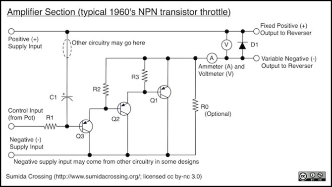
Power Amplifier
This first diagram shows the amplifier section. This looks rather different from modern designs for two reasons: first, it’s using NPN transistors typical of the time, rather than the PNP transistor found in today’s throttles. This means that the output is actually a variable negative voltage rather than a variable positive one, but it really doesn’t matter because positive and negative are defined relative to each other, and the reversing control is going to switch the two anyway. The motor won’t care.
One non-obvious feature of these throttles is that the supply voltage was often 18 - 20+ volts DC, but what actually ended up on the track was a variable voltage of around 0 - 12 volts DC (at least in HO and N throttles), due to losses in various components and the way the transistors were used.
Another major difference is the use of multiple transistors in a cascade. This is to deal with limitations of transistor gain. In fact, a throttle for O-scale use would more typically have had a fourth transistor. Q1 is the actual power transistor, and Q2, Q3 are for additional gain of the control signal (which comes from the throttle circuit, which may be a simple potentiometer or something more). Actually a modern transistor used in throttles is typically a Darlington transistor, which is a two-transistor cascade within a single case, for exactly the same reasons.
Resistors R2 and R3 are to deal with leakage current in the transistors, a problem that could result in thermal runaway and destruction of the transistors if not addressed. Diode D1 is a protection device, in case another throttle was connected to the same block with reversed voltage, to short circuit it (and trip its protection circuit) rather than exposing the transistors to a reversed voltage that could damage them.
C1 can be connected in a variety of ways, but its basic function is to damp out high-frequency oscillations that could cause problems with television and radio receivers. Depending on how it’s connected it can also provide a low-frequency pulse for smoother low-speed running if a pulse generator is not used, similar to the connection to the AC line in the MRC power pack described last week.
R0 is a rather interesting feature, obsolete today. It was based on the November 1961 article Dirt Cutting Device for the Transistor Throttle. And its purpose was to let full voltage through in a very brief spike if something prevented the motor from drawing current. The resistor would then limit current to a relatively low value that wouldn’t affect the motor’s operation. The intent was to burn through non-conductive oxide spots on the rails, which was a problem with brass rail. As use of nickel-silver rail became more prevalent in the 1960’s, the need for this feature waned. It also wouldn’t work with lit cars since the bulbs would limit current (and it would probably do bad things to modern LED lighting).
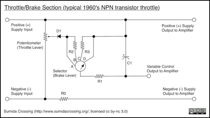
Throttle and Brake
This next diagram shows the main controls: the throttle and brake levers (levers were typical of these designs, to replicate prototypical control stands). This is a relatively simple system, and many were far more complex. This circuit would be connected between a filtered DC power supply on the left and the amplifier section on the right. Resistor R0 isn’t strictly part of the throttle, but instead serves as a safety current limiter to the power amplifier.
In this design, the throttle lever is connected to a potentiometer, and the output of that goes to a selector switch which provides the various braking positions. Diode D1 is to prevent reversed voltages from making it into this circuit and on to the transistor, which could be damaged as a result.
The brake selector switch shown here has four positions. Often the resistors R2 and R3 would be adjustable (rheostats) to allow the degree of action to be fine-tuned, but fixed values could be used. Position A bypasses the brake, giving a more immediate response to the throttle, and was often omitted, as position B provided more realistic operation (it also wasn’t needed if B used a rheostat and could be turned down to zero resistance).
Position B is the “Release” position. Set here, track power would gradually ramp up to the level set by the throttle, replicating the slow release of the train brakes and gradual acceleration of the train. Position C is the “Service” position. Set here, track power would gradually be reduced as the control output rose to the full “positive” level (in an NPN throttle, a full control voltage means zero track power since we’re varying the negative side and this makes the difference between the two zero volts). The Service position replicated the normal behavior of applying brakes to gradually reduce speed.
Finally position D provided for much faster braking, limited only by the value of R1 (small relative to R2 and R3), and this replicated an emergency stop. This was still a gradual stop, to prevent cars from derailing. The reverser switch typically had a neutral position that disconnected the power from the track (similar to a modern Kato Power pack), and this could be used to prevent a train running into another or some similar serious disaster where derailing cars was acceptable.
Other Elements
Beyond the basic throttle and amplifier sections, there would be a filtered power supply, producing DC (typically heavily filtered to get real DC; people didn’t realize the benefits of using rippled DC until later). A pulse generator might be added as well, feeding into the throttle/brake circuit to provide for pulsed starting power.
One interesting circuit element Westcott developed was a load-compensation circuit. This could allow a train to maintain speed when climbing and descending grades. It turned out to be a bit controversial, as many modelers wanted trains to slow and accelerate on hills, not maintain a fixed speed, to force the engineer to react to the situation. Later versions were adapted to produce more prototypical slowing and accelerating on grades than the models would do on their own.
Further Evolution
In 1965 a new technology entered the scene: the Silicon-Controlled Rectifier, or SCR. An SCR is basically a switch that can only be turned on, not off, which sounds rather useless. But when coupled with a supply of pulsed power that turns itself off every cycle, the SCR can be used to let the pulse through starting at different points in the cycle, effectively providing a control over average voltage (and average voltage is what makes the train run faster or slower).
It was possible to build pulsed throttles before the SCR, and many early designs did so, typically using unfiltered rectified DC (“ripple”) at full-wave (120 Hz) or half-wave (60 Hz) cycles, or with more sophisticated methods. But this technology made experimentation with pulse designs easier, and seems to have catalyzed interest in just what kinds of pulses worked best. In the same January 1965 issue of MR that introduced the SCR (in Pure-pulse Transistor Throttle by David Fyffe, another early throttle designer) Westcott outlined the various kinds of pulses that could be used, and their strengths and weaknesses in his article, Toward Perfect Motor Response.
Several SCR articles followed in later years, and SCR designs were still being published into the late 1970’s at least.
In 1969 Westcott published his TAT-IV design in the March issue of MR, simply titled: Improved Transistor Throttle. In this article he elaborated on his experiments with motors, noting that he’d found the ideal pulse form to be pulses of as small as 2.5 milliseconds duration, repeated every 25 milliseconds (or 40 pulses per second as he put it) to be the best for avoiding vibration and noise in the motor while minimizing heating. He also noted that pulses were really only needed when starting (or coming down to very low speed) and needed to be replaced with filtered DC at higher speeds to avoid damage.
As an example of how complex things had become, the TAT-IV design contained a total of eleven transistors. The TAT-III had used five (three output, one for voltage regulation, and one for load compensation).
Interestingly, while he was using 12V DC as the 100% throttle level (ramping up to that from zero), at low speed the pulses he used were 18 to 20 volt square waves. Later work (which I haven’t tracked down) would show that square waves at these frequencies weren’t really a good idea, leading to arcing on the commutator and excessive heating. And later SCR designs used “ripple” pulses with more gradual rise and fall profiles.
In fact one of the interesting problems with pulses was that they made the wheels spin or jerk, which tended to polish both wheels and rail, leading to poorer performance. This was also minimized by removing the pulses at higher speeds.
Modern DCC decoders use square waves, but at least in ultrasonic decoders they use them at much higher frequencies (15,000 Hz instead of 40 Hz) and this minimizes both the jerking effect (and the noise and vibration) as well as the heating effect.
The TAT-IV and other designs would be elaborated further in the 1970’s, and other designers were trying new ideas as well, but the major design innovations all seem to have taken place in about one decade, over the course of the 1960’s. What came in the next decade was refinement, at least until the next technological revolution, command control, began.
Aside from his own innovation in the field, Westcott’s editorial policy of publishing such “electronic hobbyist” articles undoubtedly helped promote the development of the transistor throttle, and his work with pulsed-output designs helped model trains evolve into the smooth-running machines we know today. He may not have invented the transistor throttle, but his contributions to it really can’t be overstated.