


Kato DC Power Pack
Several years ago I investigated several DC power packs, including one of my Kato packs (I have three of them). At the time I was reluctant to take one apart because the screws are hidden under the glued-on feet. But a question on the JNS Forum spurred me to investigate the circuitry more closely, and so I took one apart. And in the process, I discovered that some of my old information was wrong.
At the time, I was using my old oscilloscope, and it had some accuracy issues. It was a cheap hand-held unit, and while it fundamentally works, sometimes it was a bit misleading to read. Earlier this year I bought a new scope, and now I can’t blame any mistakes on my tools. it’s all down to me.
The old scope seemed to show a gap between successive pulses, leading me to suspect that the pack was only letting half the cycle through. The reality, as shown in the trace below from my new scope, is that it’s allowing both cycles through, and merely doing the common trick of rectifying them so both will be positive.
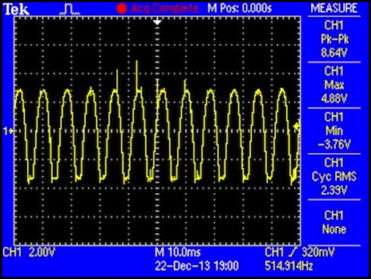
And no, I don’t know why the scope thinks half the cycle is “negative”. It isn’t. Given the circuit, it can’t be. But I still haven’t fully figured out how the scope works.
My new oscilloscope (which I’ve had for about 10 months now) is a Tektronix TBS 1042, a good 2-channel, 40 MHz student/hobbyist scope. Since most of what I do is with circuits operating at kilohertz frequencies it’s really more than I need, but it has the capability to handle things at low-megahertz frequencies, which I might need playing with some micro-processor circuitry for things like Arduinos.
The Kato Pack
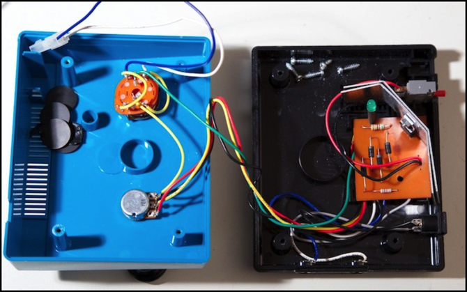
I opened up my Kato pack, simply by prying the rubber feet off with a screwdriver and then removing four screws. Inside, as seen at the top of the post, there’s a single circuit board wired to the controls, the power input (bottom right) and accessory output (center bottom), and one big transistor on a heat sink. There’s also the track power output (wired to the reversing switch, top left) and a LED mounted on the circuit board so it sticks up through the top of the case, to show that power’s on.
Kato uses an external “wall wart” type transformer, which puts out a nominal 15V RMS AC. My actual measurement shows that on a 120.0 V house supply (yep, 120.0, I measured it) it was producing 17.0 V RMS AC, but that will undoubtedly drop a volt or two with a real load. Because of the way the power pack is built, you could actually use a 15V DC power supply (or even a 12V DC one), although as we’ll see in a bit, that’s not as good as AC.
Inside, the circuit is pretty simple:
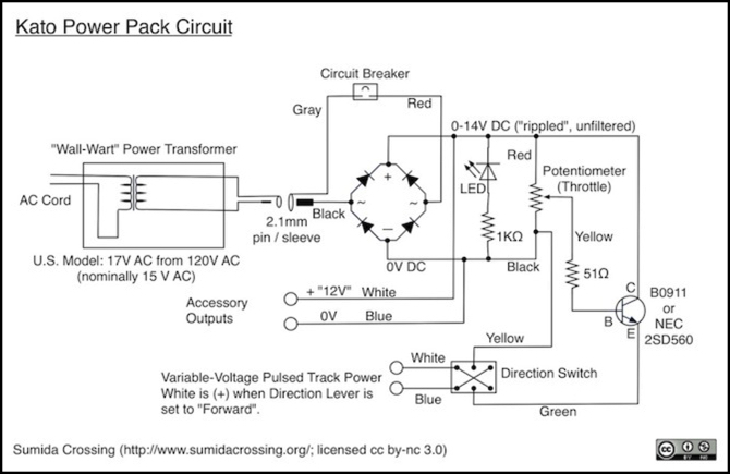
First, the AC is converted to DC by four diodes arranged as a full-wave bridge rectifier. The output of this is DC, but because there’s no filtering it’s really just the AC wave with half the peaks flipped (as can be seen in the scope trace up above; that’s the track output with a train on it, but it’s basically the rectifier output).
Note: the diodes are marked “V73 RL20”, but aside from one Chinese reference to an RL20x series of power diodes, I can’t find any information on them. The Chinese ones are rated for 2.0 amps, safely above what this circuit would need.
The output of the rectifier is used for three things: first, it’s tapped to provide the two “12V” accessory contacts on the side of the power pack. Second, a LED with a 1 KOhm resistor is attached between them. This glows if there’s power. Finally, the power goes to the train-control circuitry.
The resettable circuit-breaker on the back of the power-pack (gray box top right) is inline on the input, so any problems causing a short, on the track, on an accessory, or inside the pack, will cause it to trip.
Kato’s DC power-pack has only two controls: a direction switch (top left), and a throttle knob (lower left). The direction switch is an A/off/B dual-throw switch wired as a reverser, so it can be used to turn the track power off, as well as reversing direction. Because track power is done parallel to the accessory outputs, changing polarity or turning off track power does not affect the accessory outputs.
The throttle knob is connected to a potentiometer, and the output of that (which is low-current) is used to control the power transistor, which is the big, black, circuit element with a heat sink. This acts as an amplifier, letting larger voltages through to the track as the pot is turned.
My copy of the power transformer was marked “B0911”, but I’ve seen photos on a Japanese blog showing a similar Kato pack (Japanese version) with a NEC 2SD560 chip. The specs aren’t quite identical, but the difference is probably more one of available supplies than any functional difference. While Japanese AC is slightly lower voltage than U.S. AC, their external transformers for each market probably convert both to the same DC voltage, and that’s what the transistor uses.
What’s missing from this circuit is any filtering, so rather than getting a flat DC voltage at the track, you actually get what the scope trace up above shows: a series of pulses from zero to as much as 13.0 volts (peak) that is really the original AC waveform, converted to one polarity. That’s actually good, because at low speeds DC motors run better on “pulsed” power, because the voltage is higher for a given power quantity, which tends to overcome friction in the motor and drivetrain while still producing a low speed once things get turning.
Accessories also get that, but most accessories aren’t going to be bothered. It would not, however, be a good idea to run digital circuitry off the Kato power pack accessory output. Transistors and such aren’t going to deal well with power that keeps dropping to zero every 8 milliseconds.
One consequence of this is that the power pack’s operation really doesn’t depend on whether the external power transformer is putting out an AC or DC voltage. The first thing that happens is either gets converted to DC. If you have an old “wall wart” with a 2.1mm output and around 12-16 volts at 500 to 1,000 mA (0.5 to 1.0 A), it should work just fine. I tried this out with one of my 12V DC lighting power supplies, and my test loco ran around the “workbench” (dinning room table) test track just fine (slower than it did with the usual supply, but it had no problem with power otherwise).
Note that DC has one downside: you won’t get pulsed power, so the slowest slow-speed won’t be as slow on a DC supply as it would with an AC supply. Kato has a reputation for “smooth” power from their power packs. I suspect that’s really about how smoothly their potentiometer-based transistor throttle varies the output power. The actual voltage is anything but smooth. And that’s a good thing.